Difference between revisions of "Test Tasks"
m (→About) |
m |
||
| Line 93: | Line 93: | ||
* [http://community.elphel.com/files/imu/java/ Reference Java Program] - with built-in log parser | * [http://community.elphel.com/files/imu/java/ Reference Java Program] - with built-in log parser | ||
* [http://community.elphel.com/files/imu/read_imu_log.php_txt Log parser written in PHP] | * [http://community.elphel.com/files/imu/read_imu_log.php_txt Log parser written in PHP] | ||
| + | [[Category:IMU]] | ||
Revision as of 10:03, 5 October 2012
Contents
Area: IMU Data Processing
About
"An Inertial Measurement Unit (IMU) is an electronic device that measures and reports on a craft's velocity, orientation, and gravitational forces, using a combination of accelerometers and gyroscopes, sometimes also magnetometers..." © Wikipedia
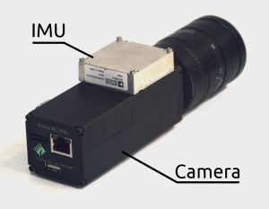
We use ADIS16375 (fully compatible with ADIS16488) with a tri-axis gyroscope and a tri-axis accelerometer.
Our projects
1. Images Relative Orientation
The goal is to find how the camera rotated/moved (Rotation Matrix) between the shots. Knowing the images' relative orientation allows to use this information for further 3D reconstruction.
2. ERS Correction
Our sensor is Aptina's MT9P006 - CMOS, 5MP, 1/2.5". It has an ERS (Electronic Rolling Shutter) - the image scan time is about 1/15 s (~66 ms) while IMU samples data at 2.460 kHz (T = 0.406 ms) which makes it possible to reconstruct how the camera moved during the image acquisition and correct the ERS effect by placing each pixel according to the sensor orientation at each moment of time. This only corrects the movement/rotation of the camera but not the ERS effect from the fast moving objects.
Test Tasks
Input Data
- ADIS16375 Datasheet
- Reference Java Program - with an already written parser.
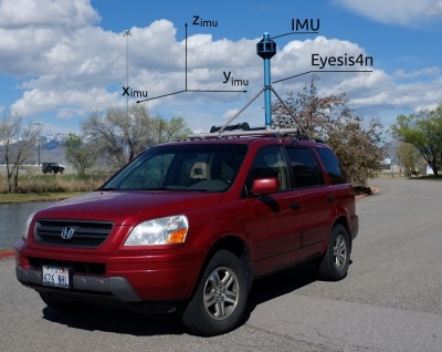
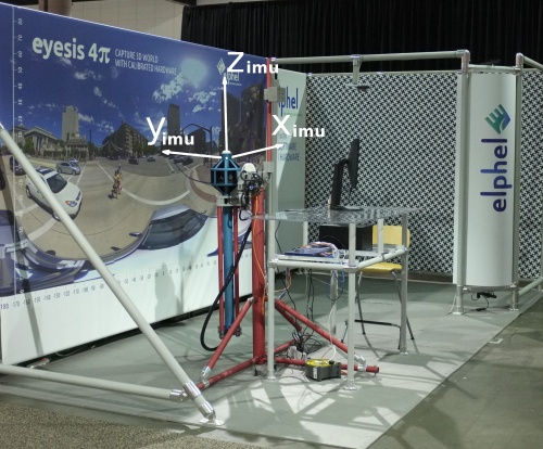
- Calibration Data of an Eyesis4π camera:
- Camera_parameters.csv - just to look up some constants that might be needed: lenses parameters, calibration machine (goniometer) parameters.
- ImageSet_orientation.csv
timestamp - timestamp of an image set taken at certain camera orientation during the calibration process. Seconds since January 1, 1970, the Time Zone is GMT
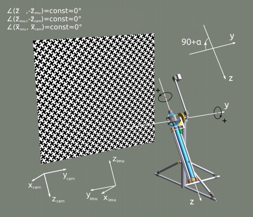
axial - angle in degrees about Z-axis (Fig.3)
tilt - angle in degrees about Y-axis (Fig.3)
Motor2 - motor 2 state in its steps
Motor3 - motor 3 state in its steps
NumPoints - applies to images only
RMS - applies to images only
- Calibration binary log files - test.log-00001...00015:
A log file contains 3 types of records (events):
  a. (2.460kHz) IMU data
      - [localTimeStamp,GMT]: IMU:[gyroX][gyroY][gyroZ][angleX][angleY][angleZ][accelX][accelY][accelZ][veloX][veloY][veloZ][temperature]
      where original parameters are angular velocities and accelerations - delta angles and delta velocities represent an integration of original parameters.
  b. (5Hz) GPS data
      - [localTimeStamp,GMT]: GPS: $GPRMC,231112.2,A,4043.36963,N,11155.90616,W,000.00,089.0,250811,013.2,E
  c. (rare) Image-acquired event registered at local clock.
      - [localTimeStamp,GMT]: SRC: [masterTimeStamp,GMT][localTimeStamp,GMT],
      knowing the master's timestamp is important for matching the events with the taken images - each image has a master timestamp in its EXIF header.
      The local timestamp is just the time at which an event was registered.
Requirements
- Programming language - Java
Task 1. Parse the IMU Data
Description
- The IMU model is ADIS16375.
- Learn how the log data parser works from the reference Java program.
- Modify or write your own parser and plot the IMU data in a spreadsheet as Value(Time) (for accelerations and angular velocities) or Sum(Time) (for delta angles and delta velocities) for a given log file.
Comments
-
Output
A spreadsheet with plotted data.
Task 2. Estimating biases (zero drifts) of the IMU Data
Description
- Determine the time intervals of when the camera is at rest.
- Estimate the average biases (zero drifts) of ADIS16375 IMU output data when at rest. The formulas can be retrieved from the reference program.
Comments
- The Camera-IMU system can be considered at rest within some time range from the image registration event - SRC-record in the log file. This range is also to be determined/estimated.
- The first SRC-record is found in test.log-00002.
Output
Estimated zero drifts stored in a public variable and in an XML file.
Task 3. Calculating the IMU parameters more precisely
Description
- Calculate the IMU parameters with a better precision using the IMU data log files and the calibration machine orientation log - ImageSet_orientation.csv
Comments
- Calculate the relative IMU rotation matrices for each state at which the pictures were acquired considering the calibration machine angles to be precise enough.
- Knowledge of the precise initial IMU orientation is not needed - can be defined arbitrarily.
- The first SRC-record is found in test.log-00002.
Output
Calculated with a better precision IMU parameters in a public variable and in an XML file.
Links
- 10338 Sensor board
- IMU ADIS16488 Datasheet
- Calibration Data for an Eyesis4π camera
- Reference Java Program - with built-in log parser
- Log parser written in PHP


