Difference between revisions of "Focus adjustment 393"
From ElphelWiki
(→regular SFE) |
|||
| Line 14: | Line 14: | ||
# adjust screws | # adjust screws | ||
# repeat from 4. until good | # repeat from 4. until good | ||
| + | |||
| + | ==Setup== | ||
| + | ===Parts=== | ||
| + | * Assembled SFE without lens and without IR-cut filter (can be with the filter if the target lens is different) | ||
| + | * M12 adapter | ||
| + | * 2 spacers: 5mm and 4.7mm (shaved off 0.3mm (made from 5mm spacer) for optimal adjustment) | ||
| + | * Lens N125B04530W with IR-cut filter. If the target lens is different, still use this one for adjustment then replace. Wrap the thread of the lens with the teflon tape for better thread fitting - 2 layers if enough. When screwing in make sure the tape does not get in the optical path. | ||
| + | {| | ||
| + | |[[File:SFE focusing parts.jpeg|thumb|500px|Fig.2 SFE parts]] | ||
| + | |} | ||
| + | * Focus adjustment screws - do not overtighten initially. Later, right before starting the procedure when the camera is against the pattern - turn it on, while in jpeg open the control interface and adjust the screws for the best manual focus (do not apply too much force). | ||
| + | {| | ||
| + | |[[File:SFE focusing SFE screws.jpeg|thumb|200px|Fig.3 Focus adjustment screws]] | ||
| + | |} | ||
| + | ===Assembled setup=== | ||
| + | * Take a longer cable - at least 100mm | ||
| + | * Connect to port 0 | ||
| + | * Set the camera address to 192.168.0.38 | ||
| + | * Make sure the power supply provides the right voltage - 12V or 48V. If possible install PoE compatible power board - 10386. | ||
| + | {| | ||
| + | |[[File:SFE focusing camera.jpeg|thumb|200px|Fig.4 Assembled focusing setup]] | ||
| + | |} | ||
| + | ===Pattern=== | ||
| + | * Use the wallpaper pattern | ||
| + | {| | ||
| + | |valign='top'|[[File:SFE focusing tripod.jpeg|thumb|200px|Fig.5 Tripod placement]] | ||
| + | |valign='top'|[[File:SFE focusing tripod closer.jpeg|thumb|200px|Fig.6 Tripod closeup]] | ||
| + | |} | ||
| + | * Make sure all 4 lasers are pointing in the right spots - "manual laser pointers" yellow button in the imagej plugin | ||
| + | {| | ||
| + | |valign='top'|[[File:SFE focusing laser spots.jpeg|thumb|200px|Fig.7 Laser spot markings]] | ||
| + | |} | ||
Revision as of 10:49, 2 October 2020
Description
internal use
regular SFE
- used on big the Xeon PC - 192.168.0.6
- restore from test_focusing/default.conf-xml
- quick get&show
- find grid
- no-move measure
- show PSF
- adjust screws
- repeat from 4. until good
Setup
Parts
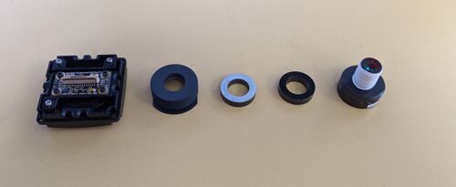
- Assembled SFE without lens and without IR-cut filter (can be with the filter if the target lens is different)
- M12 adapter
- 2 spacers: 5mm and 4.7mm (shaved off 0.3mm (made from 5mm spacer) for optimal adjustment)
- Lens N125B04530W with IR-cut filter. If the target lens is different, still use this one for adjustment then replace. Wrap the thread of the lens with the teflon tape for better thread fitting - 2 layers if enough. When screwing in make sure the tape does not get in the optical path.
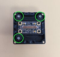
- Focus adjustment screws - do not overtighten initially. Later, right before starting the procedure when the camera is against the pattern - turn it on, while in jpeg open the control interface and adjust the screws for the best manual focus (do not apply too much force).
Assembled setup
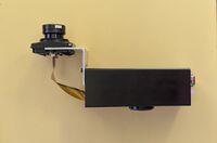
- Take a longer cable - at least 100mm
- Connect to port 0
- Set the camera address to 192.168.0.38
- Make sure the power supply provides the right voltage - 12V or 48V. If possible install PoE compatible power board - 10386.
Pattern
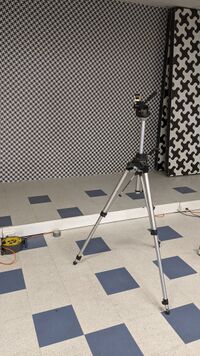
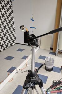
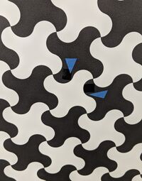
- Use the wallpaper pattern
- Make sure all 4 lasers are pointing in the right spots - "manual laser pointers" yellow button in the imagej plugin

