Difference between revisions of "JP4 HDR"
From ElphelWiki
| Line 50: | Line 50: | ||
{| border="0" cellpadding="2" align="right" | {| border="0" cellpadding="2" align="right" | ||
|- | |- | ||
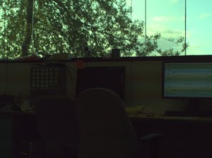
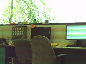
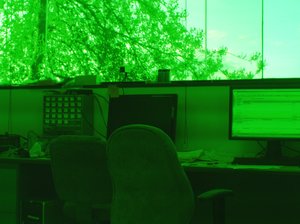
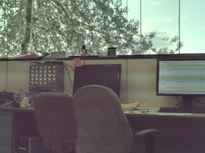
| − | | [[Image:Hdr02 all gain1.jpeg|thumb|150px nonHDR image with gain=1]] || [[Image:Hdr02 all gain16.jpeg|thumb|150px nonHDR image with gain=16]] || [[Image:Hdr02.jpeg|thumb|150px HDR source image with gained G2]] || [[Image:Hdr02 processed.jpg|thumb|150px processed HDR image]] | + | | [[Image:Hdr02 all gain1.jpeg|thumb|150px nonHDR image with global analog gain=1]] || [[Image:Hdr02 all gain16.jpeg|thumb|150px nonHDR image with global analog gain=16]] || [[Image:Hdr02.jpeg|thumb|150px HDR source image with gained G2]] || [[Image:Hdr02 processed.jpg|thumb|150px processed HDR image]] |
|- | |- | ||
|} | |} | ||
Revision as of 13:05, 16 February 2009
HDR JP4
Bayer pattern look like this
| R | G1 | R | G1 | R | G1 |
| G2 | B | G2 | B | G2 | B |
| R | G1 | R | G1 | R | G1 |
| G2 | B | G2 | B | G2 | B |
| R | G1 | R | G1 | R | G1 |
| G2 | B | G2 | B | G2 | B |
Some sensors have possibility to set independed scale to G1 and G2. Considering that the accessible optics does not give the full permission of a sensor resolution, it can be used for increase in a dynamic range of a image sensor.


