Difference between revisions of "10398"
| (19 intermediate revisions by 2 users not shown) | |||
| Line 1: | Line 1: | ||
==10398== | ==10398== | ||
| − | [[Image:10398_top.png| thumb | 374px| 10398 board, top view]] | + | [[Image:10398_top.png|thumb|374px|10398 board, top view]] |
| − | [[Image:10398_bottom.png| thumb | 374px| 10398 board, bottom view]] | + | [[Image:10398_bottom.png|thumb|374px|10398 board, bottom view]] |
| − | 10398 board is a 14MPix sensor front end (SFE) designed to work with [[10393]] camera system board. It has the same physical dimensions and the same optical format (1/2.3") as a 5MPix SFE [[10338D]]. | + | 10398 board is a 14MPix sensor front end (SFE) designed to work with [[10393]] camera system board. It has the same physical dimensions and the same optical format (1/2.3") as a 5MPix SFE [[10338D]] (15mm x 28mm). |
| − | The 14MPix (4608H x 3288V, 1.4μm x1.4 μm) image sensor used is On Semiconductor (former Aptina) [http://www.onsemi.com/pub_link/Collateral/MT9F002-D.PDF | + | The 14MPix (4608H x 3288V, 1.4μm x1.4 μm) image sensor used is On Semiconductor (former Aptina) [http://www.onsemi.com/pub_link/Collateral/MT9F002-D.PDF MT9F002]. This sensor (and 10398 SFE) uses 4-lane HiSPi serial interface running at 700 Mbps/lane and is capable of running at 13.7 fps at full resolution (12bpp mode), or 60fps at 2304x1296 (1080p + 20% EIS). Other combinations of resolution/frame rate are possible. |
| + | |||
| + | Up to 4 10398 SFE can be directly connected to [[10393]] system board and run simultaneously at full speed (880M pixels/s combined). | ||
10398 SFE uses the same 30-pin flex cable connector for control (I²C, extra GPIO), differential data output (4-lane HiSPi+clock) and 3.3V power (additional 2.8V analog and 1.8V digital are generated on board). Short connections can use general purpose flex jumpers (30 conductors, 0.5mm pitch) or Elphel flex cables manufactured for the parallel interface sensors, longer connections require controlled-impedance flex cables with 100Ω differential lines. | 10398 SFE uses the same 30-pin flex cable connector for control (I²C, extra GPIO), differential data output (4-lane HiSPi+clock) and 3.3V power (additional 2.8V analog and 1.8V digital are generated on board). Short connections can use general purpose flex jumpers (30 conductors, 0.5mm pitch) or Elphel flex cables manufactured for the parallel interface sensors, longer connections require controlled-impedance flex cables with 100Ω differential lines. | ||
| − | [[Media:10398. | + | [[Media:10398.pdf|10398 Circuit Diagram, Parts List]] <br/> |
| + | [[Media:10398_gerber.tar.gz|10398 Gerber files]] <br/> | ||
| + | [[Media:10398_assy.tar.gz|10398 component placement files]] | ||
| + | |||
| + | ===MT9F002 Application Notes=== | ||
| + | ====Slave mode==== | ||
| + | To enable: | ||
| + | # R0x301A[8]=1 | ||
| + | # R0x3026[9:7]=0x1 for GPI1, after this step sensor operates in GPI1 triggered GRR switching to free running (ERS) | ||
| + | # (undocumented) R0x3158[15]=1 - most likely '''slave mode enable''' - after this step senor operates in slave mode GRR | ||
| + | # (undocumented) R0x3158[13]=1 - disable GRR? - after this step senor operates in slave mode, readouts on rising GPI1, see Fig.3 | ||
| + | |||
| + | {| | ||
| + | |[[File:Mt9f002 slave mode.jpeg|700px|thumb|Fig.3 Slave mode]] | ||
| + | |} | ||
| + | |||
| + | ====I2C commands via sysfs==== | ||
| + | root@elphel393:~# cd /sys/devices/soc0/elphel393-sensor-i2c\@0/ | ||
| + | * read (port 0): | ||
| + | echo "mt9f002 0x0 0x3000" > i2c0 | ||
| + | cat i2c0 | ||
| + | * write: | ||
| + | echo "mt9f002 0x0 0x301a 0x011c" > i2c0 | ||
| + | |||
| + | ====Measure frame timing==== | ||
| + | root@elphel393:~# cd /usr/local/verilog/; test_mcntrl.py @hargs-after | ||
| + | |||
| + | //0x21 | ||
| + | // x393_status_sens_io_t - [22] time_busy | ||
| + | //0x40 | ||
| + | // x393_status_sensor_timing_t - [23:0] quad_cycles | ||
| + | //0x40a | ||
| + | // x393_sensio_jtag_t | ||
| + | // 0s are ok for other bits | ||
| + | // timing_to : 2; // [11:10] (0) Measuring sensor time to: 0 - sof, 1 - eof, 2 - sol, 3 eol | ||
| + | // timing_from : 2; // [13:12] (0) Measuring sensor time from: 0 - sof, 1 - eof, 2 - sol, 3 eol | ||
| + | // lane_num : 2; // [15:14] (0) Measuring sensor time on lane 0..3 | ||
| + | // timing_start: 1; // [ 16] (0) Start sensor timing measurement | ||
| + | |||
| + | |||
| + | // measure time from sof to sol, lane 0 | ||
| + | write_control_register 0x40a 0x10800 | ||
| + | // sof to eof | ||
| + | write_control_register 0x40a 0x10400 | ||
| + | // sol to eol | ||
| + | write_control_register 0x40a 0x12c00 | ||
| + | // eof to sof | ||
| + | write_control_register 0x40a 0x11000 | ||
| + | // eol to sol | ||
| + | write_control_register 0x40a 0x13800 | ||
| + | |||
| + | // sol to sol | ||
| + | write_control_register 0x40a 0x12800 | ||
| + | |||
| + | // sof to sof | ||
| + | '''write_control_register 0x40a 0x10000''' | ||
| + | |||
| + | // eof to eof | ||
| + | write_control_register 0x40a 0x11800 | ||
| + | |||
| + | |||
| + | // sof to sol | ||
| + | write_control_register 0x40a 0x10800 | ||
| + | |||
| + | // eol to eof | ||
| + | write_control_register 0x40a 0x13400 | ||
| + | |||
| + | read_status 0x21 | ||
| + | |||
| + | read_status 0x40 | ||
| + | |||
| + | [[Category: Boards 393]] | ||
Latest revision as of 12:44, 3 August 2018
Contents
[hide]10398
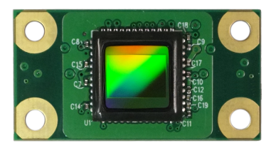
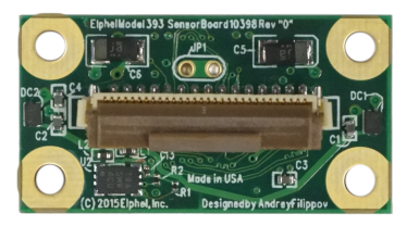
10398 board is a 14MPix sensor front end (SFE) designed to work with 10393 camera system board. It has the same physical dimensions and the same optical format (1/2.3") as a 5MPix SFE 10338D (15mm x 28mm).
The 14MPix (4608H x 3288V, 1.4μm x1.4 μm) image sensor used is On Semiconductor (former Aptina) MT9F002. This sensor (and 10398 SFE) uses 4-lane HiSPi serial interface running at 700 Mbps/lane and is capable of running at 13.7 fps at full resolution (12bpp mode), or 60fps at 2304x1296 (1080p + 20% EIS). Other combinations of resolution/frame rate are possible.
Up to 4 10398 SFE can be directly connected to 10393 system board and run simultaneously at full speed (880M pixels/s combined).
10398 SFE uses the same 30-pin flex cable connector for control (I²C, extra GPIO), differential data output (4-lane HiSPi+clock) and 3.3V power (additional 2.8V analog and 1.8V digital are generated on board). Short connections can use general purpose flex jumpers (30 conductors, 0.5mm pitch) or Elphel flex cables manufactured for the parallel interface sensors, longer connections require controlled-impedance flex cables with 100Ω differential lines.
10398 Circuit Diagram, Parts List
10398 Gerber files
10398 component placement files
MT9F002 Application Notes
Slave mode
To enable:
- R0x301A[8]=1
- R0x3026[9:7]=0x1 for GPI1, after this step sensor operates in GPI1 triggered GRR switching to free running (ERS)
- (undocumented) R0x3158[15]=1 - most likely slave mode enable - after this step senor operates in slave mode GRR
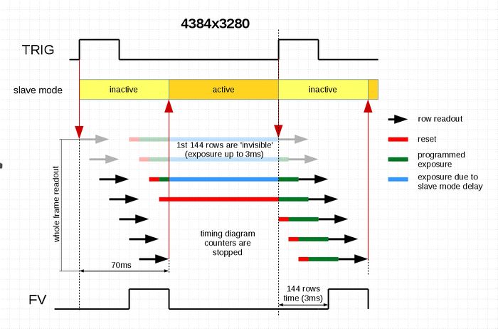
- (undocumented) R0x3158[13]=1 - disable GRR? - after this step senor operates in slave mode, readouts on rising GPI1, see Fig.3
I2C commands via sysfs
root@elphel393:~# cd /sys/devices/soc0/elphel393-sensor-i2c\@0/
- read (port 0):
echo "mt9f002 0x0 0x3000" > i2c0
cat i2c0
- write:
echo "mt9f002 0x0 0x301a 0x011c" > i2c0
Measure frame timing
root@elphel393:~# cd /usr/local/verilog/; test_mcntrl.py @hargs-after
//0x21
//       x393_status_sens_io_t - [22] time_busy
//0x40
//       x393_status_sensor_timing_t - [23:0] quad_cycles
//0x40a
//       x393_sensio_jtag_t
//           0s are ok for other bits
//           timing_to   : 2; // [11:10] (0) Measuring sensor time to: 0 - sof, 1 - eof, 2 - sol, 3 eol
//           timing_from : 2; // [13:12] (0) Measuring sensor time from: 0 - sof, 1 - eof, 2 - sol, 3 eol
//           lane_num    : 2; // [15:14] (0) Measuring sensor time on lane 0..3
//           timing_start: 1; // [   16] (0) Start sensor timing measurement


// measure time from sof to sol, lane 0
write_control_register 0x40a 0x10800
// sof to eof
write_control_register 0x40a 0x10400
// sol to eol
write_control_register 0x40a 0x12c00
// eof to sof
write_control_register 0x40a 0x11000
// eol to sol
write_control_register 0x40a 0x13800

// sol to sol
write_control_register 0x40a 0x12800

// sof to sof
write_control_register 0x40a 0x10000

// eof to eof
write_control_register 0x40a 0x11800


// sof to sol
write_control_register 0x40a 0x10800

// eol to eof
write_control_register 0x40a 0x13400

read_status 0x21

read_status 0x40


