Difference between revisions of "Trigger 393"
(→internal connectors) |
(→External connector) |
||
| (13 intermediate revisions by 2 users not shown) | |||
| Line 1: | Line 1: | ||
==<font color="blue">Description</font>== | ==<font color="blue">Description</font>== | ||
| − | 10389 board is required. | + | [[10389]] board is required (and possibly [[103891]]). |
| − | + | Use cases: | |
| + | * Trigger a single camera from external source | ||
| + | * Synchronize multiple cameras to a master camera or external trigger source | ||
| + | * Program frame rate | ||
| + | |||
| + | The conditions of the trigger can be generated either internally or externally: | ||
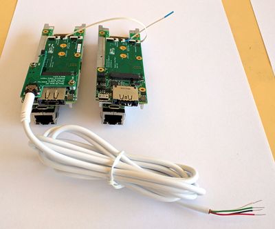
| + | * for external triggering a [[103891]] board and a 4-conductor 2.5mm audio plug with cable (example: [http://www.digikey.com/products/en?keywords=839-1029-ND digikey]) is required. | ||
| + | * for internal triggering use J4-J6 connectors with a 4-pin flex cable: J4 - internal trigger source (also transmits timestamps that can be decoded by other cameras), J5-6 - receive trigger | ||
To program trigger go to: '''http://192.168.0.9/parsedit.php => External Trigger Controls''' | To program trigger go to: '''http://192.168.0.9/parsedit.php => External Trigger Controls''' | ||
| Line 52: | Line 59: | ||
* http://192.168.0.9/parsedit.php?sensor_port=0&immediate&TRIG_CONDITION=0&TRIG_OUT=0x66555&TRIG_PERIOD=25000000&TRIG=4 | * http://192.168.0.9/parsedit.php?sensor_port=0&immediate&TRIG_CONDITION=0&TRIG_OUT=0x66555&TRIG_PERIOD=25000000&TRIG=4 | ||
| − | ===External trigger receive=== | + | ===External trigger receive (with possible self-triggering loop)=== |
| − | * http://192.168.0.9/parsedit.php?sensor_port=0&immediate&TRIG_CONDITION=0x95555&TRIG_OUT=0x66555&TRIG_PERIOD=100000000&TRIG=4 | + | Here, internal generator is routed to sync the cable output wires. |
| + | '''If the output wires are connected to the input wires (red+black and white+green) the camera will be self-triggering. ''' | ||
| + | If the wires are not connected - use external source - apply "plus" to black, "minus" to green ([[103891|check colors and pinout]]): | ||
| + | |||
| + | http://192.168.0.9/parsedit.php?sensor_port=0&immediate&TRIG_CONDITION=0x95555&TRIG_OUT=0x66555&TRIG_PERIOD=100000000&TRIG=4 | ||
| + | * at the same time the fpga generator outputs a 1 fps signal - if the sync cable wires are properly connected the camera can be triggered from this 'external' signal | ||
| + | |||
| + | ===External trigger receive (external source only)=== | ||
| + | The sync cable wires can be looped or not - does not matter. | ||
| + | http://192.168.0.9/parsedit.php?sensor_port=0&immediate&TRIG_CONDITION=0x95555&TRIG_OUT=0x66555&TRIG_PERIOD=100000000&TRIG=4 | ||
* at the same time the fpga generator outputs a 1 fps signal - if the sync cable wires are properly connected the camera can be triggered from this 'external' signal | * at the same time the fpga generator outputs a 1 fps signal - if the sync cable wires are properly connected the camera can be triggered from this 'external' signal | ||
| Line 94: | Line 110: | ||
==<font color="blue">10389 trigger testing</font>== | ==<font color="blue">10389 trigger testing</font>== | ||
| − | === | + | ===External connector=== |
In this test the camera triggers itself via audio cable. For cable wiring see [[103891]]. | In this test the camera triggers itself via audio cable. For cable wiring see [[103891]]. | ||
* To test: | * To test: | ||
| − | http://192.168.0.9/parsedit.php?sensor_port=0&immediate&TRIG_CONDITION=0&TRIG_OUT=0x66555&TRIG_PERIOD=25000000&TRIG=4 | + | - connect a sensor to port 0 |
| + | - http://192.168.0.9/parsedit.php?sensor_port=0&immediate&TRIG_CONDITION=0&TRIG_OUT=0x66555&TRIG_PERIOD=25000000&TRIG=4 | ||
visual: LED is blinking | visual: LED is blinking | ||
software: frame counter is running | software: frame counter is running | ||
| − | * It's easy to modify the cable to trigger itself and other multiple cameras. | + | * It's easy to modify the cable to trigger itself and other multiple cameras by connecting together red and black wires (+) and white with green (-). For self-testing (external trigger loop back) it is sufficient, for LED - connect anode to "+" (red+black), cathode - to "-" (white+green). |
{| | {| | ||
| Line 107: | Line 124: | ||
|} | |} | ||
| − | ===internal connectors=== | + | Turn on external trigger loop back (cable should be inserted): |
| + | http://192.168.0.9/parsedit.php?sensor_port=0&immediate&TRIG_CONDITION=0x80000&TRIG_OUT=0x66555&TRIG_PERIOD=25000000&TRIG=4 | ||
| + | |||
| + | Or use interactive page: | ||
| + | http://192.168.0.9/parsedit.php?sensor_port=0&embed=0.25&title=Parameters+for+groups:+trigger+&TRIG&TRIG_MASTER&TRIG_CONDITION=0x80000&TRIG_DELAY&TRIG_OUT=0x66555&TRIG_PERIOD=25000000&TRIG_BITLENGTH&EXTERN_TIMESTAMP&XMIT_TIMESTAMP&TRIG_DECIMATE&THIS_FRAME&refresh | ||
| + | |||
| + | And then click "Apply" button. | ||
| + | |||
| + | Both variants should turn camera into external loop back mode with 0.25s period (4 fps). If the page (and the camera) hangs, the loop is not working. For troubleshooting you may restart the camera, open | ||
| + | http://192.168.0.9/parsedit.php?sensor_port=0&embed=0.25&title=Parameters+for+groups:+trigger+&TRIG&TRIG_MASTER&TRIG_CONDITION=0&TRIG_DELAY&TRIG_OUT=0x66555&TRIG_PERIOD=25000000&TRIG_BITLENGTH&EXTERN_TIMESTAMP&XMIT_TIMESTAMP&TRIG_DECIMATE&THIS_FRAME&refresh | ||
| + | |||
| + | and press "apply". The camera will continue using internal trigger (TRIG_CONDITION=0) but still generate trigger output (TRIG_OUT=0x66555). This output can be controlled by either the LED soldered to the cable or the oscilloscope (ground to the green+white, signal - red+black - it should show not just a pulse but a encoded timestamp some 22us long. Changing TRIG_CONDITION to 0x80000 (enter 80000 into "New value/Hex" field without "0x" and press "Apply") should activate loop back, and if it works then "Refresh" button should cause new "THIS_FRAME" field value. If it does not work - trigger input does not reach camera - bad cable or connector. | ||
| + | |||
| + | ===Internal connectors=== | ||
In this test the camera triggers itself via 4-pin flex cable. | In this test the camera triggers itself via 4-pin flex cable. | ||
* Connect as displayed on the pictures below. | * Connect as displayed on the pictures below. | ||
| Line 116: | Line 146: | ||
- http://192.168.0.9/parsedit.php?sensor_port=0&immediate&TRIG_CONDITION=0x8000&TRIG_OUT=0x66555&TRIG_PERIOD=25000000&TRIG=4 | - http://192.168.0.9/parsedit.php?sensor_port=0&immediate&TRIG_CONDITION=0x8000&TRIG_OUT=0x66555&TRIG_PERIOD=25000000&TRIG=4 | ||
software: frame counter is running | software: frame counter is running | ||
| − | + | * To sync multiple camera, example: | |
| + | cable 1: camera1 (J4) -> camera2 (J6) | ||
| + | cable 2: camera2 (J5) -> camera3 (J6) | ||
| + | cable 3: camera3 (J5) -> camera4 (J6) | ||
| + | etc. | ||
{| | {| | ||
|valign='top'|[[File:10389 intsync selftest.jpeg|thumb|400px]] | |valign='top'|[[File:10389 intsync selftest.jpeg|thumb|400px]] | ||
| Line 122: | Line 156: | ||
|} | |} | ||
| + | ===Sync example: from external to internal (chaining)=== | ||
| + | * The simplest synchronization would be making a custom audio cable to sync all cameras in the system | ||
| + | * In case there are multiple cameras in the same enclosure it might make sense to sync them by chaining using 4-pin flex cables | ||
| + | {| | ||
| + | |valign='top'|[[File:10389 sync example 1.jpeg|thumb|400px]] | ||
| + | |} | ||
[[Category:393]] | [[Category:393]] | ||
Latest revision as of 10:45, 10 April 2022
Contents
- 1 Description
- 2 Parameters
- 3 Examples
- 3.1 Internal periodic trigger (10 fps, from fpga generator)
- 3.2 Internal periodic trigger (4 fps, from fpga generator) + output the signal to external port
- 3.3 External trigger receive (with possible self-triggering loop)
- 3.4 External trigger receive (external source only)
- 3.5 Recover from missing external trigger signal to internal trigger
- 3.6 Manual triggering from PC
- 4 Links
- 5 10389 trigger testing
Description
10389 board is required (and possibly 103891).
Use cases:
- Trigger a single camera from external source
- Synchronize multiple cameras to a master camera or external trigger source
- Program frame rate
The conditions of the trigger can be generated either internally or externally:
- for external triggering a 103891 board and a 4-conductor 2.5mm audio plug with cable (example: digikey) is required.
- for internal triggering use J4-J6 connectors with a 4-pin flex cable: J4 - internal trigger source (also transmits timestamps that can be decoded by other cameras), J5-6 - receive trigger
To program trigger go to: http://192.168.0.9/parsedit.php => External Trigger Controls
NOTE: Be careful with changing parameters when TRIG=4. Camera drivers are driven by the frame sync interrupts from the sensor, so if the sensor is not triggered - everything can get stuck. The Program Ahead value sets the number of frame sync interrupts the camera will wait wait for until a parameter is reprogrammed.
Parameters
| parameter | description |
| TRIG | Trigger mode. 0x0 - free running, 0x4 - triggered by external signal or FPGA timing generator, 0x14 - triggered in GRR mode |
| TRIG_MASTER | Master sensor_port (0..3) for triggering setup, other ports will have settings duplicated |
| TRIG_CONDITION | FPGA trigger sequencer trigger condition, 0 - internal, else dibits: 00 - do not use, 01 - keep, 10 - active low, 11 - active high for each GPIO[9:0] pin). 10389 board inverts signals, so 0x80000 - input from external connector, 0x08000 - input from internal flex cable (as in Eyesis) |
| TRIG_DELAY | FPGA trigger sequencer trigger delay, 32 bits in pixel clocks (100MHz or 10ns) |
| TRIG_OUT | FPGA trigger sequencer trigger output to GPIO, dibits: 00 - do not use, 01 - keep, 10 - active low GPIO output, 11 - active high GPIO output. 10389 board inverts signals, so 0x02000 - output to external connector (active high), 0x20000 - output to internal flex connector |
| TRIG_PERIOD | FPGA trigger sequencer output sync period (32 bits, in pixel clocks (100MHz or 10ns)). 0- stop. 1 - single, >=256 repetitive with specified period |
| TRIG_BITLENGTH | Bit length minus 1 (in pixel clock cycles) when transmitting/receiving timestamps, without timestamps the output pulse width is 8*(TRIG_BITLENGTH+1). Legal values 2..255 |
| EXTERN_TIMESTAMP | When 1 camera will use external timestamp (received over inter-camera synchronization cable) if it is available (no action when external syncronization is not connected), when 0 - local timestamp will be used |
| XMIT_TIMESTAMP | Specify output signal sent through internal/external connector (defined by TRIG_OUT). 0 - transmit just sync pulse (8*(TRIG_BITLENGTH+1) pixel clock periods long), 1 - pulse+timestamp 64*(TRIG_BITLENGTH+1) pixel clock periods long |
Examples
Internal periodic trigger (10 fps, from fpga generator)
- http://192.168.0.9/parsedit.php?sensor_port=0&immediate&TRIG_CONDITION=0&TRIG_PERIOD=10000000&TRIG=4
Internal periodic trigger (4 fps, from fpga generator) + output the signal to external port
External trigger receive (with possible self-triggering loop)
Here, internal generator is routed to sync the cable output wires. If the output wires are connected to the input wires (red+black and white+green) the camera will be self-triggering. If the wires are not connected - use external source - apply "plus" to black, "minus" to green (check colors and pinout):
http://192.168.0.9/parsedit.php?sensor_port=0&immediate&TRIG_CONDITION=0x95555&TRIG_OUT=0x66555&TRIG_PERIOD=100000000&TRIG=4
- at the same time the fpga generator outputs a 1 fps signal - if the sync cable wires are properly connected the camera can be triggered from this 'external' signal
External trigger receive (external source only)
The sync cable wires can be looped or not - does not matter.
http://192.168.0.9/parsedit.php?sensor_port=0&immediate&TRIG_CONDITION=0x95555&TRIG_OUT=0x66555&TRIG_PERIOD=100000000&TRIG=4
- at the same time the fpga generator outputs a 1 fps signal - if the sync cable wires are properly connected the camera can be triggered from this 'external' signal
Recover from missing external trigger signal to internal trigger
- http://192.168.0.9/parsedit.php?sensor_port=0&immediate&TRIG_CONDITION=0*-2
- *-2 - apply value parameter in the current frame (if not specified, the default is 3)
Manual triggering from PC
Enable
http://192.168.0.9:2323/trig/pointers
- TRIG=4 should be set in advance
- The command automatically sets a single-shot trigger mode with TRIG_PERIOD=0x1, but it writes the register directly into the FPGA,
not updating the TRIG_PERIOD in the PHP interface:
http://192.168.0.9/parsedit.php?TRIG&TRIG_CONDITION&TRIG_DELAY&TRIG_OUT&TRIG_PERIOD&TRIG_BITLENGTH&EXTERN_TIMESTAMP&XMIT_TIMESTAMP&refresh
Trigger/Refresh
http://192.168.0.9:8081/trig/pointers
Check status
http://192.168.0.9/parsedit.php?immediate&TRIG&TRIG_PERIOD&SENS_AVAIL&FRAME
Disable
Update the TRIG_PERIOD in the current frame
Update the TRIG_PERIOD from the user interface
- http://192.168.0.9/parsedit.php?TRIG&TRIG_CONDITION&TRIG_DELAY&TRIG_OUT&TRIG_PERIOD&TRIG_BITLENGTH&EXTERN_TIMESTAMP&XMIT_TIMESTAMP&refresh
- Refresh until the changes are applied (with Program Ahead = 3 it's 3 times):
http://192.168.0.9:8081/trig/pointers
Links
10389 trigger testing
External connector
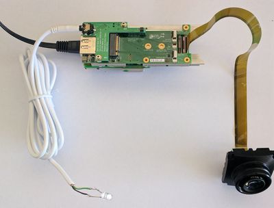
In this test the camera triggers itself via audio cable. For cable wiring see 103891.
- To test:
- connect a sensor to port 0
- http://192.168.0.9/parsedit.php?sensor_port=0&immediate&TRIG_CONDITION=0&TRIG_OUT=0x66555&TRIG_PERIOD=25000000&TRIG=4
visual: LED is blinking
software: frame counter is running
- It's easy to modify the cable to trigger itself and other multiple cameras by connecting together red and black wires (+) and white with green (-). For self-testing (external trigger loop back) it is sufficient, for LED - connect anode to "+" (red+black), cathode - to "-" (white+green).
Turn on external trigger loop back (cable should be inserted):
http://192.168.0.9/parsedit.php?sensor_port=0&immediate&TRIG_CONDITION=0x80000&TRIG_OUT=0x66555&TRIG_PERIOD=25000000&TRIG=4
Or use interactive page:
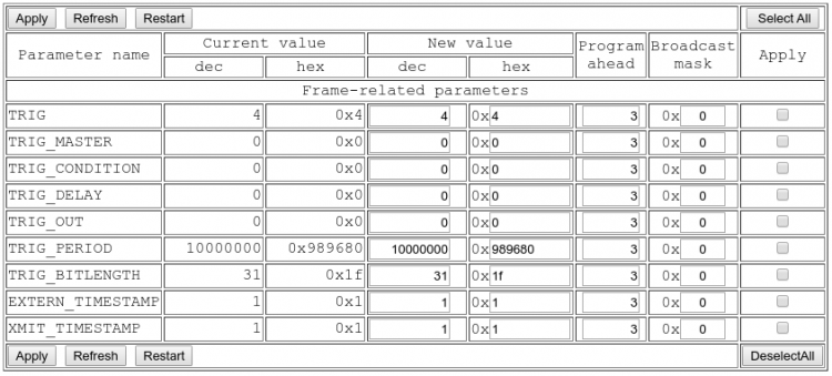
http://192.168.0.9/parsedit.php?sensor_port=0&embed=0.25&title=Parameters+for+groups:+trigger+&TRIG&TRIG_MASTER&TRIG_CONDITION=0x80000&TRIG_DELAY&TRIG_OUT=0x66555&TRIG_PERIOD=25000000&TRIG_BITLENGTH&EXTERN_TIMESTAMP&XMIT_TIMESTAMP&TRIG_DECIMATE&THIS_FRAME&refresh
And then click "Apply" button.
Both variants should turn camera into external loop back mode with 0.25s period (4 fps). If the page (and the camera) hangs, the loop is not working. For troubleshooting you may restart the camera, open
http://192.168.0.9/parsedit.php?sensor_port=0&embed=0.25&title=Parameters+for+groups:+trigger+&TRIG&TRIG_MASTER&TRIG_CONDITION=0&TRIG_DELAY&TRIG_OUT=0x66555&TRIG_PERIOD=25000000&TRIG_BITLENGTH&EXTERN_TIMESTAMP&XMIT_TIMESTAMP&TRIG_DECIMATE&THIS_FRAME&refresh
and press "apply". The camera will continue using internal trigger (TRIG_CONDITION=0) but still generate trigger output (TRIG_OUT=0x66555). This output can be controlled by either the LED soldered to the cable or the oscilloscope (ground to the green+white, signal - red+black - it should show not just a pulse but a encoded timestamp some 22us long. Changing TRIG_CONDITION to 0x80000 (enter 80000 into "New value/Hex" field without "0x" and press "Apply") should activate loop back, and if it works then "Refresh" button should cause new "THIS_FRAME" field value. If it does not work - trigger input does not reach camera - bad cable or connector.
Internal connectors
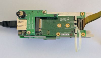
In this test the camera triggers itself via 4-pin flex cable.
- Connect as displayed on the pictures below.
- J4 - trigger output (master port)
- J5-J6 - trigger input (slave ports)
- To test:
- connect a sensor to port 0
- http://192.168.0.9/parsedit.php?sensor_port=0&immediate&TRIG_CONDITION=0x8000&TRIG_OUT=0x66555&TRIG_PERIOD=25000000&TRIG=4
software: frame counter is running
- To sync multiple camera, example:
cable 1: camera1 (J4) -> camera2 (J6)
cable 2: camera2 (J5) -> camera3 (J6)
cable 3: camera3 (J5) -> camera4 (J6)
etc.
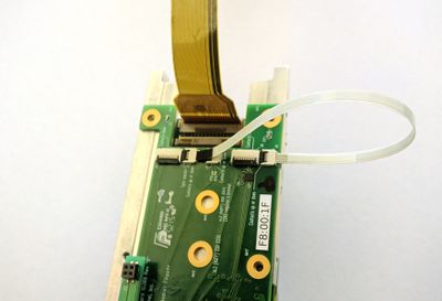
Sync example: from external to internal (chaining)
- The simplest synchronization would be making a custom audio cable to sync all cameras in the system
- In case there are multiple cameras in the same enclosure it might make sense to sync them by chaining using 4-pin flex cables
