Difference between revisions of "Boot options 393"
| Line 53: | Line 53: | ||
===Other boot options=== | ===Other boot options=== | ||
The instructions are defined by the 3 options above. | The instructions are defined by the 3 options above. | ||
| − | They | + | They define where the camera will load the u-boot, device tree and kernel from: μSD card or NAND flash. The location of rootfs ("/") is set in the device tree. Available locations for rootfs: |
| − | * any μSD card | + | * any μSD card partition. The default device tree parameter is: |
bootargs = "cma=336M console=ttyPS0,115200 root=/dev/mmcblk0p2 rw ip=192.168.0.9 earlyprintk rootwait rootfstype=ext4"; | bootargs = "cma=336M console=ttyPS0,115200 root=/dev/mmcblk0p2 rw ip=192.168.0.9 earlyprintk rootwait rootfstype=ext4"; | ||
* any NAND flash partition. The default parameter is: | * any NAND flash partition. The default parameter is: | ||
bootargs = "cma=336M console=ttyPS0,115200 root=ubi0:elphel393-rootfs rw ip=192.168.0.9 earlyprintk rootwait rootfstype=ubifs ubi.mtd=4,2048"; | bootargs = "cma=336M console=ttyPS0,115200 root=ubi0:elphel393-rootfs rw ip=192.168.0.9 earlyprintk rootwait rootfstype=ubifs ubi.mtd=4,2048"; | ||
| − | * any partition | + | * any partition of the internal SSD (if installed). There is no default device tree. |
| + | * RAM, but it was tested a while ago: | ||
| + | bootargs = "cma=336M console=ttyPS0,115200 root=/dev/ram rw ip=192.168.0.8 earlyprintk ramdisk_size=262144"; | ||
| + | |||
| + | '''To build a custom device tree''', see [http://wiki.elphel.com/index.php?title=Poky_2.0_manual SDK manual]''' | ||
| − | |||
==<font color="blue">cp210x_gpio.py -h</font>== | ==<font color="blue">cp210x_gpio.py -h</font>== | ||
Revision as of 18:01, 15 December 2016
Contents
Description
Normally camera boots from the internal NAND flash memory, and it is always possible to boot it from the micro SD card, so even corruption of files on the internal flash will not "brick" the system. There are no buttons or switches on the camera - it should be instructed to change the boot source. Always booting from micro SD is not practical - in that case it would not be possible to leave a non-bootable card (intended just for image/video storage) in the camera slot.
There are two ways to switch camera to the micro SD boot mode.
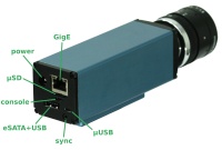
One requires camera to be connected to the host computer with the USB cable (micro USB socket under the network jack - marked "console" on the picture). There is an internal USB-to-serial converter in the camera (CP2103) that offers 4 additional GPIO signals in addition to just the serial connection. One of these signals selects the boot source (GPIO0 - 0 - MMC, 1 - NAND), another (GPIO3 - 0 reset, 1 - normal operation). Unfortunately GPIO control of the CP2103 is not in a mainline cp210x Linux driver so this functionality requires a modified version (see instructions below).
Another way to "tell" the camera to boot from the μSD card instead of the internal NAND flash is to use a mechanically modified card or card adapter (such cards are provided with the camera). Standard specifies two alternative ways for detection of the card presence - one is a mechanical switch (closed when the card is inserted), another is a pull-up resistor on a data line. Camera uses both signals at boot time to determine the boot source:
- Switch not closed, pull-up resistor not detected -> no card present, boot from the internal NAND flash
- Switch closed -> data (non-bootable) card present, boot from the internal NAND flash
- Switch not closed, pull-up resistor is detected -> bootable card present, boot from the MMC card
Boot instructions
Internal NAND flash (default)
- Make sure the recovery card is not inserted
- Power on
Recovery micro SD card
Requirements:
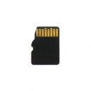
- A modified card that doesn't lock the mechanical CD pin in the slot - it's done by carefully filing off the corner (see Fig.1) - most cards have circuitry there and get damaged. Use the one that came with the camera or order a new one.
Instructions:
- insert the card, power on
Regular micro SD card
Requirements:
- μUSB-to-USB cable
- Linux: compile cp210x driver
Instructions:
- Power on
- Connect the camera's console port (see Fig.2, right under the μSD slot) to PC using μUSB-to-USB cable
- Reload the cp210x driver:
- unplug the μUSB-to-USB cable
- In the terminal from the directory where the driver was built, run:
 sudo rmmod cp210x
 sudo insmod cp210x.ko
- plug the cable back (the driver will stay loaded until the PC is rebooted).
- In the terminal from the directory where the driver was built, run:
./cp210x_gpio.py 0x6;
./cp210x_gpio.py 0xe;
- To reboot back to NAND flash w/o power cycling:
./cp210x_gpio.py 0x7;
./cp210x_gpio.py 0xf;
Other boot options
The instructions are defined by the 3 options above. They define where the camera will load the u-boot, device tree and kernel from: μSD card or NAND flash. The location of rootfs ("/") is set in the device tree. Available locations for rootfs:
- any μSD card partition. The default device tree parameter is:
bootargs = "cma=336M console=ttyPS0,115200 root=/dev/mmcblk0p2 rw ip=192.168.0.9 earlyprintk rootwait rootfstype=ext4";
- any NAND flash partition. The default parameter is:
bootargs = "cma=336M console=ttyPS0,115200 root=ubi0:elphel393-rootfs rw ip=192.168.0.9 earlyprintk rootwait rootfstype=ubifs ubi.mtd=4,2048";
- any partition of the internal SSD (if installed). There is no default device tree.
- RAM, but it was tested a while ago:
bootargs = "cma=336M console=ttyPS0,115200 root=/dev/ram rw ip=192.168.0.8 earlyprintk ramdisk_size=262144";
To build a custom device tree, see SDK manual
cp210x_gpio.py -h
$./cp210x_gpio.py -h
usage: cp210x_gpio.py [-h] [-d DEVICE] [-m MASK] [gpio_value]

positional arguments:
 gpio_value            hex value for GPIO. Example (GPIO[3:0]): 0xf - all
                       1's, 0x0 - all 0's. If not specified - read GPIO only

optional arguments:
 -h, --help            show this help message and exit
 -d DEVICE, --device DEVICE
                       USB device. Default: /dev/ttyUSB0
 -m MASK, --mask MASK  hex value for masking out GPIO bits: 1 - enable
                       rewrite, 0 - disable. Example (GPIO[3:0]): -m 0xf

