Difference between revisions of "Trigger 393"
From ElphelWiki
(→internal connectors) |
(→10389 trigger testing) |
||
| Line 101: | Line 101: | ||
==<font color="blue">10389 trigger testing</font>== | ==<font color="blue">10389 trigger testing</font>== | ||
| − | === | + | ===External connector=== |
In this test the camera triggers itself via audio cable. For cable wiring see [[103891]]. | In this test the camera triggers itself via audio cable. For cable wiring see [[103891]]. | ||
* To test: | * To test: | ||
| Line 115: | Line 115: | ||
|} | |} | ||
| − | === | + | ===Internal connectors=== |
In this test the camera triggers itself via 4-pin flex cable. | In this test the camera triggers itself via 4-pin flex cable. | ||
* Connect as displayed on the pictures below. | * Connect as displayed on the pictures below. | ||
Revision as of 08:46, 16 October 2018
Contents
- 1 Description
- 2 Parameters
- 3 Examples
- 4 Links
- 5 10389 trigger testing
Description
10389 board is required (and possible 103891).
Use cases:
- Trigger a single camera from external source
- Synchronize multiple cameras to a master camera or external trigger source
- Program frame rate
The conditions of the trigger can be generated either internally or externally:
- for external triggering a 103891 board and a 4-conductor 2.5mm audio plug with cable (example: digikey) is required.
- for internal triggering use J4-J6 connectors with a 4-pin flex cable: J4 - internal trigger source (also transmits timestamps that can be decoded by other cameras), J5-6 - receive trigger
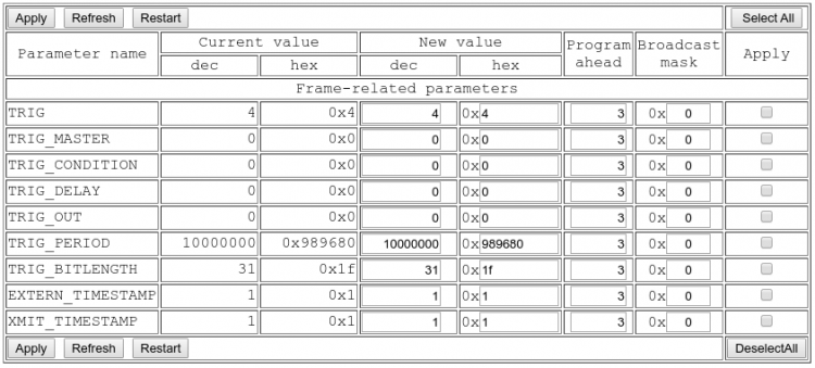
To program trigger go to: http://192.168.0.9/parsedit.php => External Trigger Controls
NOTE: Be careful with changing parameters when TRIG=4. Camera drivers are driven by the frame sync interrupts from the sensor, so if the sensor is not triggered - everything can get stuck. The Program Ahead value sets the number of frame sync interrupts the camera will wait wait for until a parameter is reprogrammed.
Parameters
| parameter | description |
| TRIG | Trigger mode. 0x0 - free running, 0x4 - triggered by external signal or FPGA timing generator, 0x14 - triggered in GRR mode |
| TRIG_MASTER | Master sensor_port (0..3) for triggering setup, other ports will have settings duplicated |
| TRIG_CONDITION | FPGA trigger sequencer trigger condition, 0 - internal, else dibits: 00 - do not use, 01 - keep, 10 - active low, 11 - active high for each GPIO[9:0] pin). 10389 board inverts signals, so 0x80000 - input from external connector, 0x08000 - input from internal flex cable (as in Eyesis) |
| TRIG_DELAY | FPGA trigger sequencer trigger delay, 32 bits in pixel clocks (100MHz or 10ns) |
| TRIG_OUT | FPGA trigger sequencer trigger output to GPIO, dibits: 00 - do not use, 01 - keep, 10 - active low GPIO output, 11 - active high GPIO output. 10389 board inverts signals, so 0x02000 - output to external connector (active high), 0x20000 - output to internal flex connector |
| TRIG_PERIOD | FPGA trigger sequencer output sync period (32 bits, in pixel clocks (100MHz or 10ns)). 0- stop. 1 - single, >=256 repetitive with specified period |
| TRIG_BITLENGTH | Bit length minus 1 (in pixel clock cycles) when transmitting/receiving timestamps, without timestamps the output pulse width is 8*(TRIG_BITLENGTH+1). Legal values 2..255 |
| EXTERN_TIMESTAMP | When 1 camera will use external timestamp (received over inter-camera synchronization cable) if it is available (no action when external syncronization is not connected), when 0 - local timestamp will be used |
| XMIT_TIMESTAMP | Specify output signal sent through internal/external connector (defined by TRIG_OUT). 0 - transmit just sync pulse (8*(TRIG_BITLENGTH+1) pixel clock periods long), 1 - pulse+timestamp 64*(TRIG_BITLENGTH+1) pixel clock periods long |
Examples
Internal periodic trigger (10 fps, from fpga generator)
- http://192.168.0.9/parsedit.php?sensor_port=0&immediate&TRIG_CONDITION=0&TRIG_PERIOD=10000000&TRIG=4
Internal periodic trigger (4 fps, from fpga generator) + output the signal to external port
External trigger receive
- http://192.168.0.9/parsedit.php?sensor_port=0&immediate&TRIG_CONDITION=0x95555&TRIG_OUT=0x66555&TRIG_PERIOD=100000000&TRIG=4
- at the same time the fpga generator outputs a 1 fps signal - if the sync cable wires are properly connected the camera can be triggered from this 'external' signal
Recover from missing external trigger signal to internal trigger
- http://192.168.0.9/parsedit.php?sensor_port=0&immediate&TRIG_CONDITION=0*-2
- *-2 - apply value parameter in the current frame (if not specified, the default is 3)
Manual triggering from PC
Enable
http://192.168.0.9:2323/trig/pointers
- TRIG=4 should be set in advance
- The command automatically sets a single-shot trigger mode with TRIG_PERIOD=0x1, but it writes the register directly into the FPGA,
not updating the TRIG_PERIOD in the PHP interface:
http://192.168.0.9/parsedit.php?TRIG&TRIG_CONDITION&TRIG_DELAY&TRIG_OUT&TRIG_PERIOD&TRIG_BITLENGTH&EXTERN_TIMESTAMP&XMIT_TIMESTAMP&refresh
Trigger/Refresh
http://192.168.0.9:8081/trig/pointers
Check status
http://192.168.0.9/parsedit.php?immediate&TRIG&TRIG_PERIOD&SENS_AVAIL&FRAME
Disable
Update the TRIG_PERIOD in the current frame
Update the TRIG_PERIOD from the user interface
- http://192.168.0.9/parsedit.php?TRIG&TRIG_CONDITION&TRIG_DELAY&TRIG_OUT&TRIG_PERIOD&TRIG_BITLENGTH&EXTERN_TIMESTAMP&XMIT_TIMESTAMP&refresh
- Refresh until the changes are applied (with Program Ahead = 3 it's 3 times):
http://192.168.0.9:8081/trig/pointers
Links
10389 trigger testing
External connector
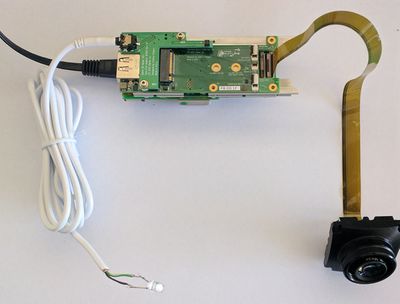
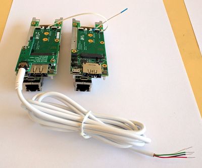
In this test the camera triggers itself via audio cable. For cable wiring see 103891.
- To test:
- connect a sensor to port 0
- http://192.168.0.9/parsedit.php?sensor_port=0&immediate&TRIG_CONDITION=0&TRIG_OUT=0x66555&TRIG_PERIOD=25000000&TRIG=4
visual: LED is blinking
software: frame counter is running
- It's easy to modify the cable to trigger itself and other multiple cameras.
Internal connectors
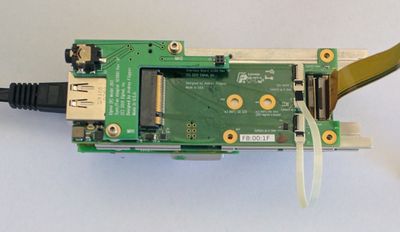
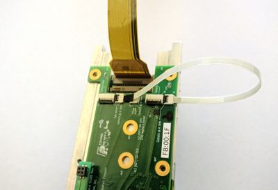
In this test the camera triggers itself via 4-pin flex cable.
- Connect as displayed on the pictures below.
- J4 - trigger output (master port)
- J5-J6 - trigger input (slave ports)
- To test:
- connect a sensor to port 0
- http://192.168.0.9/parsedit.php?sensor_port=0&immediate&TRIG_CONDITION=0x8000&TRIG_OUT=0x66555&TRIG_PERIOD=25000000&TRIG=4
software: frame counter is running
- To sync multiple camera, example:
cable 1: camera1 (J4) -> camera2 (J6)
cable 2: camera2 (J5) -> camera3 (J6)
cable 3: camera3 (J5) -> camera4 (J6)
etc.
Sync example: from external to internal (chaining)
- The simplest synchronization would be making a custom audio cable to sync all cameras in the system
- In case there are multiple cameras in the same enclosure it might make sense to sync them by chaining using 4-pin flex cables
