Difference between revisions of "Elphel camera parts"
From ElphelWiki
| Line 39: | Line 39: | ||
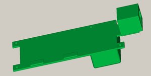
=== 0353-10 - bottoms === | === 0353-10 - bottoms === | ||
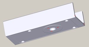
==== 0353-10-01 - camera bottom, l=104.77mm ==== | ==== 0353-10-01 - camera bottom, l=104.77mm ==== | ||
| + | {| border="0" cellpadding="2" | ||
| + | |- | ||
| + | | [[Image:0353-10-01.jpeg|thumb|[[Media:0353-10-01.stp.tar.gz|3d (step)]] [[Media:0353-10-01.dxf.tar.gz|2d (dxf)]] [[Media:0353-10-01.pdf|2d (pdf)]]]] || | ||
| + | |- | ||
| + | |} | ||
=== 0353-11 - tops === | === 0353-11 - tops === | ||
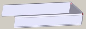
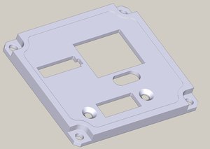
==== 0353-11-01 - camera top plain (no connector holes), l=104.77mm ==== | ==== 0353-11-01 - camera top plain (no connector holes), l=104.77mm ==== | ||
| + | {| border="0" cellpadding="2" | ||
| + | |- | ||
| + | | [[Image:0353-11-01.jpeg|thumb|[[Media:0353-11-01.stp.tar.gz|3d (step)]] [[Media:0353-11-01.dxf.tar.gz|2d (dxf)]] [[Media:0353-11-01.pdf|2d (pdf)]]]] || | ||
| + | |- | ||
| + | |} | ||
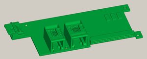
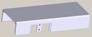
==== 0353-11-02 - camera top with connector holes for the 10369 (serial port, optoisolated I/O), l=104.77mm ==== | ==== 0353-11-02 - camera top with connector holes for the 10369 (serial port, optoisolated I/O), l=104.77mm ==== | ||
| + | {| border="0" cellpadding="2" | ||
| + | |- | ||
| + | | [[Image:0353-11-02.jpeg|thumb|[[Media:0353-11-02.stp.tar.gz|3d (step)]] [[Media:0353-11-02.dxf.tar.gz|2d (dxf)]] [[Media:0353-11-02.pdf|2d (pdf)]]]] || | ||
| + | |- | ||
| + | |} | ||
=== 0353-12 - front ends === | === 0353-12 - front ends === | ||
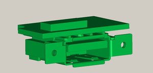
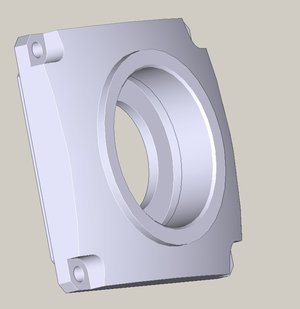
==== 0353-12-01 - Sensor front end for 10318/10338 boards ==== | ==== 0353-12-01 - Sensor front end for 10318/10338 boards ==== | ||
| + | {| border="0" cellpadding="2" | ||
| + | |- | ||
| + | | [[Image:0353-12-01.jpeg|thumb|[[Media:0353-12-01.stp.tar.gz|3d (step)]] [[Media:0353-12-01.dxf.tar.gz|2d (dxf)]] [[Media:0353-12-01.pdf|2d (pdf)]]]] || | ||
| + | |- | ||
| + | |} | ||
=== 0353-13 - back panels === | === 0353-13 - back panels === | ||
==== 0353-13-01 - Back panel, only network (RJ45) connector ==== | ==== 0353-13-01 - Back panel, only network (RJ45) connector ==== | ||
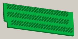
==== 0353-13-02 - Back panel, with holes for network, SATA and USB connectors ==== | ==== 0353-13-02 - Back panel, with holes for network, SATA and USB connectors ==== | ||
| + | {| border="0" cellpadding="2" | ||
| + | |- | ||
| + | | [[Image:0353-13-02.jpeg|thumb|[[Media:0353-13-02.stp.tar.gz|3d (step)]] [[Media:0353-13-02.dxf.tar.gz|2d (dxf)]] [[Media:0353-13-02.pdf|2d (pdf)]]]] || ''Notes:Most individual components are not shown in the model.'' | ||
| + | |- | ||
| + | |} | ||
Revision as of 12:33, 2 June 2008
Contents
[hide]0353-00 - PCB assemblies
0353-00-01 - 10353 rev E assembly
| Notes:Most individual components are not shown in the model. |
0353-00-02 - 10369 rev A assembly
| Notes:Most individual components are not shown in the model. |
0353-00-03 - 103693 rev A assembly
| Notes:Most individual components are not shown in the model. |
0353-00-04 - 103691 rev A assembly
| Notes:Most individual components are not shown in the model. |
0353-01 - cable assemblies
0353-02 - other electronic assemblies
0353-02-01 - CF card
Major camera enclosure parts
0353-10 - bottoms
0353-10-01 - camera bottom, l=104.77mm
0353-11 - tops
0353-11-01 - camera top plain (no connector holes), l=104.77mm
0353-11-02 - camera top with connector holes for the 10369 (serial port, optoisolated I/O), l=104.77mm
0353-12 - front ends
0353-12-01 - Sensor front end for 10318/10338 boards
0353-13 - back panels
0353-13-01 - Back panel, only network (RJ45) connector
0353-13-02 - Back panel, with holes for network, SATA and USB connectors
| Notes:Most individual components are not shown in the model. |
