Difference between revisions of "Trigger 353"
From ElphelWiki
| Line 34: | Line 34: | ||
====Internal==== | ====Internal==== | ||
* TRIG_CONDITION=0x0 | * TRIG_CONDITION=0x0 | ||
| + | * set the TRIG_PERIOD | ||
* TRIG=0x4 | * TRIG=0x4 | ||
| − | |||
OR | OR | ||
Revision as of 12:10, 18 May 2010
Description
10369 board is required.
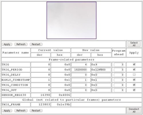
The triggering is used for one or several cameras synchronization or FPS control. The conditions of the trigger can be generated either internally or externally. For external triggering a phone cable with RJ14 is used. To program trigger go to: http://192.168.0.9/parsedit.php -> External Trigger Controls
Parameters
| parameter | description |
| TRIG | Trigger mode enable. Currently 0 - free running, 4 - triggered by external signal or internal FPGA timing generator. |
| TRIG_PERIOD | FPGA trigger sequencer output sync period (32 bits, in pixel clocks). 0- stop. 1..256 - single, >=256 repetitive with specified period |
| TRIG_DELAY | FPGA trigger sequencer trigger delay, 32 bits in pixel clocks |
| EARLY_TIMESTAMP | When 0 - frame sync (start of the frame readout) will be used for timestamping of the images, when 1 and the trigger mode is external (physically external to the camera or just when sensor runs from the FPGA timing generator) the start of exposure will be used for time stamping (exposure time earlier). This is the default mode to prevent recorded frame period jitter caused by automatic exposure adjustments |
| TRIG_CONDITION | level) for each GPIO[11:0] pin |
| TRIG_OUT | level_when_active). Bit 24 - test mode, when GPIO[11:10] are controlled by other internal signals |
Examples
Internal
- TRIG_CONDITION=0x0
- set the TRIG_PERIOD
- TRIG=0x4
OR
- set the TRIG_PERIOD
- http://192.168.0.9/sync.php?role=detect&channel=internal
External
Receive: GPIO[10] needs to be configured to receive the trigger signal - set TRIG_CONDITION=0x200000
Generate: GPIO[11] needs to be programmed - set TRIG_OUT=0x800000
Notes:

TRIG_CONDITION: a 22-bit register where 2 bits are used for programming each GPIO (from 0 to 11, e.g., TRIG_CONDITION[1:0] will program GPIO[0]) - MSB enables input and LSB selects active  trigger signal level.

TRIG_OUT: Same as in TRIG_CONDITION register - MSB enables and LSB selects level.
OR
GPIO[11] & GPIO[10] can be set by following http://192.168.0.9/sync.php?role=detect&channel=external
