103891: Difference between revisions
Jump to navigation
Jump to search
No edit summary |
No edit summary |
||
| Line 14: | Line 14: | ||
* J2 connector: [http://www.digikey.com/product-detail/en/cui-inc/SJ1-42534-SMT-TR/CP1-42534SJTR-ND/659908 SJ1-42534-SMT-TR] ([http://www.cui.com/product/resource/sj1-4253x-smt-series.pdf datasheet]) | * J2 connector: [http://www.digikey.com/product-detail/en/cui-inc/SJ1-42534-SMT-TR/CP1-42534SJTR-ND/659908 SJ1-42534-SMT-TR] ([http://www.cui.com/product/resource/sj1-4253x-smt-series.pdf datasheet]) | ||
* Sync cable example: [http://www.digikey.com/product-detail/en/tensility-international-corp/10-00331/839-1029-ND/2350237 839-1029-ND] | * Sync cable example: [http://www.digikey.com/product-detail/en/tensility-international-corp/10-00331/839-1029-ND/2350237 839-1029-ND] | ||
{| class='wikitable' | {| class='wikitable' | ||
|+Connector pinout | |||
|Name | |||
|Pin | |||
|Cable wire color | |||
|Description | |||
|- | |||
|XSYNC1 | |XSYNC1 | ||
|pin 1 | |pin 1 | ||
|black | |black | ||
|optoisolated, "+" input with respect to XSYNC2 | |||
|- | |- | ||
|SYNC_DRV | |SYNC_DRV | ||
|pin 2 | |pin 2 | ||
|red | |red | ||
|Sync output (DC-coupled), +5V pulses with respect to GND | |||
|- | |- | ||
|GND | |GND | ||
|pin 3 | |pin 3 | ||
|white | |white | ||
|Output reference, connected to the camera system ground | |||
|- | |- | ||
|XSYNC2 | |XSYNC2 | ||
|pin 4 | |pin 4 | ||
|green | |green | ||
|optoisolated, "-" input with respect to XSYNC1 | |||
|} | |} | ||
* [[Trigger_393#Internal_periodic_trigger_.284_fps.2C_from_fpga_generator.29_.2B_output_the_signal_to_external_port|How to output trigger signal to external port]] | * [[Trigger_393#Internal_periodic_trigger_.284_fps.2C_from_fpga_generator.29_.2B_output_the_signal_to_external_port|How to output trigger signal to external port]] | ||
* [[Media:103891a.pdf|103891 Rev "A" Circuit Diagram, Parts List, PCB layout]] | * [[Media:103891a.pdf|103891 Rev "A" Circuit Diagram, Parts List, PCB layout]] | ||
* [[Media:103891a gerber.tar.gz|103891 Rev "A" Gerber files]] | * [[Media:103891a gerber.tar.gz|103891 Rev "A" Gerber files]] | ||
Revision as of 17:30, 31 January 2018
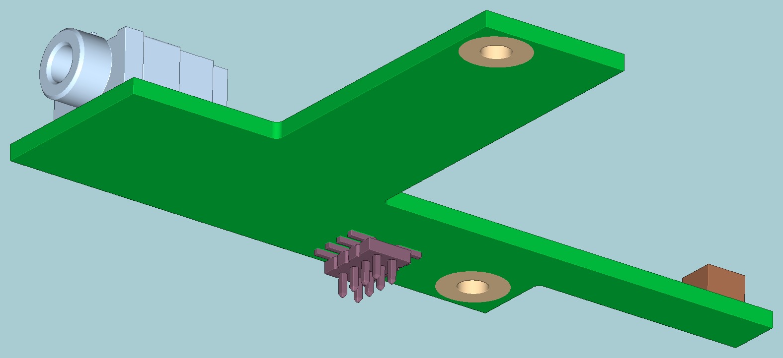
103891 adapter board routes external sync I/O from the 10389 interface board to the back panel 2.5mm barrel connector and provide 4-pic connector socket for 3.3V/5.0V fan. It is used in Elphel 393 series cameras


Mechanical properties
- Dimensions: 58 x 38 x 9 mm (all connectors installed)
- Weight: 3.0 g
- Mechanical drawings and CAD files for the 103891 board: link
|
Copyright © 2026 Elphel Inc., Licensed under [1], GNU FDL v.1.3 | ||

Links
- J2 connector: SJ1-42534-SMT-TR (datasheet)
- Sync cable example: 839-1029-ND
| Name | Pin | Cable wire color | Description |
| XSYNC1 | pin 1 | black | optoisolated, "+" input with respect to XSYNC2 |
| SYNC_DRV | pin 2 | red | Sync output (DC-coupled), +5V pulses with respect to GND |
| GND | pin 3 | white | Output reference, connected to the camera system ground |
| XSYNC2 | pin 4 | green | optoisolated, "-" input with respect to XSYNC1 |