Difference between revisions of "10331"
(add link to russian page) |
|||
| Line 4: | Line 4: | ||
[[10334]] | [[10334]] | ||
---- | ---- | ||
| + | Description on russian [[10331.Ru]] | ||
[[Image:10331_frag.png]] | [[Image:10331_frag.png]] | ||
Revision as of 17:13, 8 February 2006
Description on russian 10331.Ru
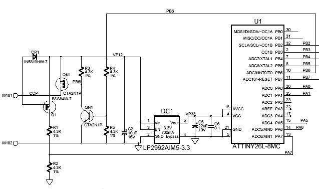
You may download complete circuit diagram, parts list and PCB layout here (pdf)
The two contacts to the camera are W101 and W102 - the golden-plated PCB pads mate with the spring contacts when the bayonet adapter is attached to the camera. W102 is grounded and W101 is driven by two MOSFET switches in the camera. Normally the high side switch connects to +12VDC providing power to the adapter. To transmit the data to adapter the high side switch is disconnected and the low side connects W101 to ground through a 1K resistor. The voltage on W101 will drop to zero, it will be detected by Q1 and transferred to port PA7 of the microcontroller U1. Adapter also can transfer data - when the high side switch in the camera is open, and low side - closed, signal on port PB6 opens both transistors QN1 and voltage on W101 goes up.
Free Software and Open Hardware. Elphel, Inc., 2005
