10369: Difference between revisions
Jump to navigation
Jump to search
No edit summary |
No edit summary |
||
| Line 119: | Line 119: | ||
| 1 || GND || || || 3 || +3.3V || | | 1 || GND || || || 3 || +3.3V || | ||
|- | |- | ||
| 2 || -48V || isolated, primary || || | | 2 || -48V || isolated, primary || || 4 || +48V || isolated, primary | ||
|- | |- | ||
|} | |} | ||
| Line 135: | Line 135: | ||
| 1 || GND || || || 3 || +3.3V || | | 1 || GND || || || 3 || +3.3V || | ||
|- | |- | ||
| 2 || -48V || isolated, primary || || | | 2 || -48V || isolated, primary || || 4 || +48V || isolated, primary | ||
|- | |- | ||
|} | |} | ||
'' '''Note:''' J4 is normally not installed. It is used in some camera modificatios where ther is another board on top of the 10369 that needs power - J4 is located oppposite to J3, same as on 10353 system board. '' | '' '''Note:''' J4 is normally not installed. It is used in some camera modificatios where ther is another board on top of the 10369 that needs power - J4 is located oppposite to J3, same as on 10353 system board. '' | ||
---- | |||
===== J5 - Power ===== | |||
{| class="wikitable" style="background:#eeeeee; " border="1" | |||
|+ Power connector (from 10353) | |||
|- | |||
! Pin !! Signal !! Notes !! !! Pin !! Signal !! Notes | |||
|- | |||
| 1 || GND || || || 3 || -48V ||isolated, primary | |||
|- | |||
| 2 || +3.3V || || || 4 || +48V || isolated, primary | |||
|- | |||
|} | |||
'' '''Note:''' J5 is normally not installed. It may be used in multi-camera systems to provide 3.3V from the commomn to all camera modules power supply (DC-DC converter on 10353 should not be installed). '' | |||
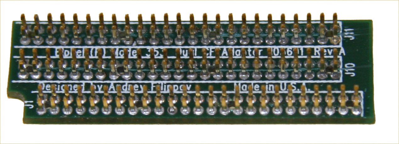
[[Image:103691_sm.jpeg|frame|[[Media:103691.jpeg|103691: Dual CF card adapter/riser board]]]] | [[Image:103691_sm.jpeg|frame|[[Media:103691.jpeg|103691: Dual CF card adapter/riser board]]]] | ||
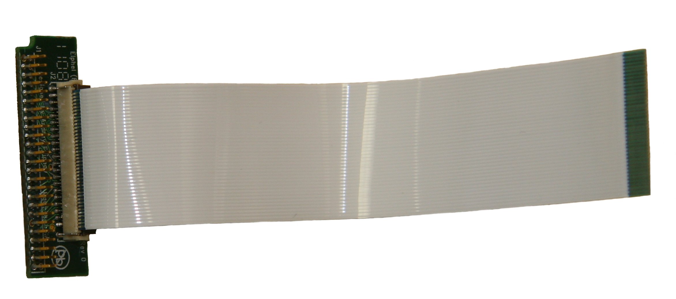
[[Image:103692_sm.jpeg|frame|[[Media:103692.jpeg|103692: 1.8" ZIF-type HDD adapter board]]]] | [[Image:103692_sm.jpeg|frame|[[Media:103692.jpeg|103692: 1.8" ZIF-type HDD adapter board]]]] | ||
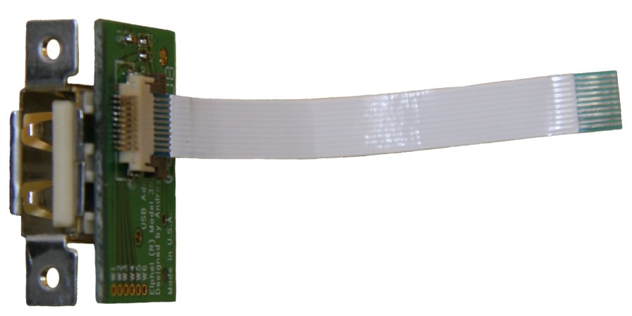
[[Image:103693_sm.jpeg|frame|[[Media:103693.jpeg|103693: External USB connector adapter board]]]] | [[Image:103693_sm.jpeg|frame|[[Media:103693.jpeg|103693: External USB connector adapter board]]]] | ||
Revision as of 06:22, 25 June 2008
10369

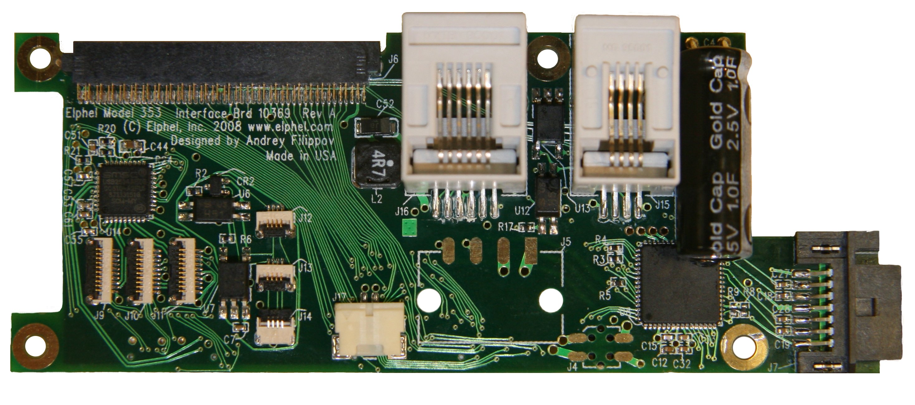

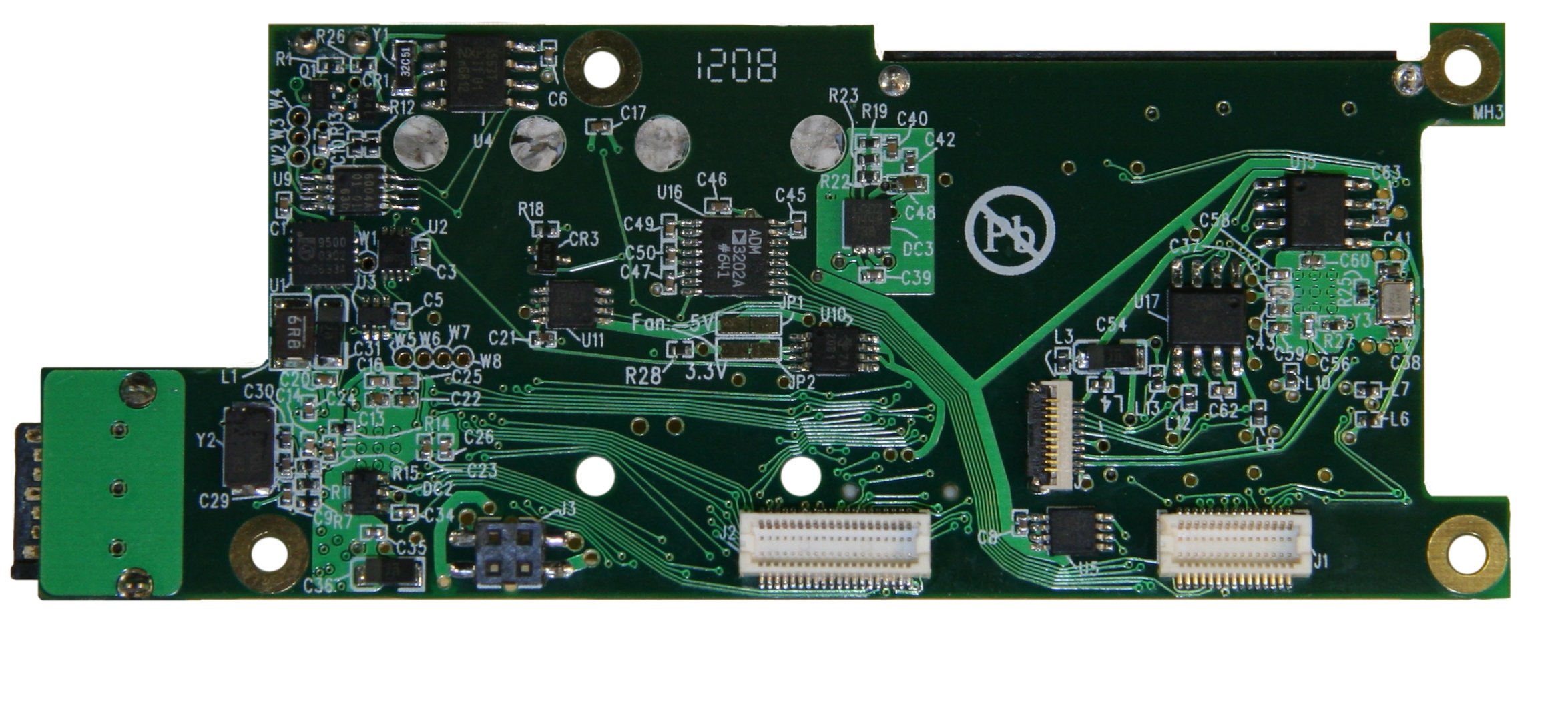

10369 interface board is an extension board for the Elphel 353/363 series cameras.
- It provides multiple interfaces and peripherals to the camera:
- SATA port for external disk drives
- Compact Flash (in "True IDE" mode) and IDE HDD ports (with adapter/riser boards: 103691, 103692)
- RS-232 port
- Opto-isolated I/O port for synchronizing the camera or synchronizing together multiple cameras (modular RJ11 external connector)
- Opto-isolated I/O port for synchronizing multiple camera modules in the same enclosure (flex cable connectors)
- Digital thermometer with internal ("system") and external thermal sensor (emitter-base junction of PNP or NPN transistor)
- Fan driver, controlled by the digital thermometer with programmable on/off temperature
- Clock/calendar with the super-capacitor backup power
- EEPROM for the board identification and configuration
Connectors
J1 - AUX
| Pin | Signal | Notes | Pin | Signal | Notes | |
|---|---|---|---|---|---|---|
| 1 | GND | 16 | EXT[10] | GPIO | ||
| 2 | GND | 17 | EXT[9] | GPIO | ||
| 3 | EXT[0] | GPIO | 18 | EXT[11] | GPIO | |
| 4 | EXT[2] | GPIO | 19 | GND | ||
| 5 | EXT[1] | GPIO | 20 | GND | ||
| 6 | EXT[3] | GPIO | 21 | CTS | RS232 | |
| 7 | GND | 22 | RTS | RS232 | ||
| 8 | GND | 23 | RXD | RS232 | ||
| 9 | EXT[4] | GPIO | 24 | TXD | RS232 | |
| 10 | EXT[6] | GPIO | 25 | +3.3V | ||
| 11 | EXT[5] | GPIO | 26 | +3.3V | ||
| 12 | EXT[7] | GPIO | 27 | U0VM | USB | |
| 13 | GND | 28 | U0VP | USB | ||
| 14 | GND | 29 | +3.3V | |||
| 15 | EXT[8] | GPIO | 30 | +3.3V |
J2 - IDE
| Pin | Signal | Notes | Pin | Signal | Notes | |
|---|---|---|---|---|---|---|
| 1 | IDE_RST | 21 | IDE_DMARQ | |||
| 2 | GND | 22 | GND | |||
| 3 | IDE_D[7] | 23 | IDE_IOW | |||
| 4 | IDE_D[8] | 24 | GND | |||
| 5 | IDE_D[6] | 25 | IDE_IOR | |||
| 6 | IDE_D[9] | 26 | GND | |||
| 7 | IDE_D[5] | 27 | IDE_IORDY | |||
| 8 | IDE_D[10] | 28 | GND | |||
| 9 | IDE_D[4] | 29 | IDE_DMACK | |||
| 10 | IDE_D[11] | 30 | GND | |||
| 11 | IDE_D[3] | 31 | IDE_INTRQ | |||
| 12 | IDE_D[12] | 32 | EXT_OE | not used | ||
| 13 | IDE_D[2] | 33 | IDE_A[1] | |||
| 14 | IDE_D[13] | 34 | -- | |||
| 15 | IDE_D[1] | 35 | IDE_A[0] | |||
| 16 | IDE_D[14] | 36 | IDE_A[2] | |||
| 17 | IDE_D[0] | 37 | IDE_CS0 | |||
| 18 | IDE_D[15] | 38 | IDE_CS1 | |||
| 19 | GND | 39 | -- | |||
| 20 | GND | 40 | GND |
J3 - Power
| Pin | Signal | Notes | Pin | Signal | Notes | |
|---|---|---|---|---|---|---|
| 1 | GND | 3 | +3.3V | |||
| 2 | -48V | isolated, primary | 4 | +48V | isolated, primary |
Note: +/- 48V are non-regulated input power rails. For 12V or 24V camera modifications these lines will also have +/-12V or +/-24V.
J4 - Power (to next boards)
| Pin | Signal | Notes | Pin | Signal | Notes | |
|---|---|---|---|---|---|---|
| 1 | GND | 3 | +3.3V | |||
| 2 | -48V | isolated, primary | 4 | +48V | isolated, primary |
Note: J4 is normally not installed. It is used in some camera modificatios where ther is another board on top of the 10369 that needs power - J4 is located oppposite to J3, same as on 10353 system board.
J5 - Power
| Pin | Signal | Notes | Pin | Signal | Notes | |
|---|---|---|---|---|---|---|
| 1 | GND | 3 | -48V | isolated, primary | ||
| 2 | +3.3V | 4 | +48V | isolated, primary |
Note: J5 is normally not installed. It may be used in multi-camera systems to provide 3.3V from the commomn to all camera modules power supply (DC-DC converter on 10353 should not be installed).