10353
From ElphelWiki
Revision as of 22:35, 13 January 2018 by Andrey.filippov (talk | contribs)
This is a legacy page. Information may not reflect the current state of the products or code.
See current products here: 10393
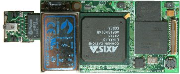
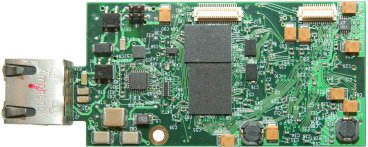
10353 processor board is the computer part of the Elphel 353/363 series cameras.
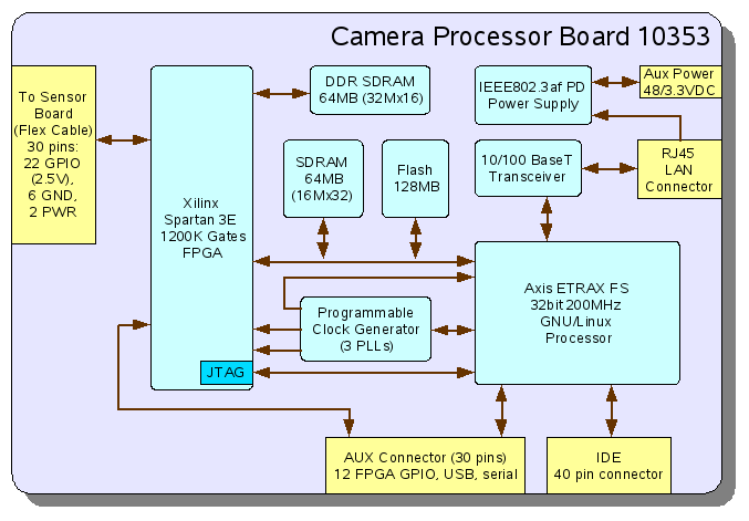
- It uses ETRAX FS processor running GNU/Linux (currently kernel 2.6.19) that has support for multiple hardware interfaces with the following of them used/connected in the Model 353:
- 10/100 Ethernet
- USB 1.1 (host)
- IDE (ATA-6)
- RS-232
- Teridian 78Q2123 is used as Ethernet PHY in the camera - it has Auto-MDI/X, so no more crossover cables are needed when connecting camera directly to a PC.
- 64MB of 32-bit white system SDRAM provide memory to run multiple applications in the camera. It is also used as a buffer for video/images and as a RAM-disk.
- 128MB of system flash memory work as a solid-state disk to boot the camera and provide it with the software. The JFFS2 file system allows writing to this "disk" data and updating the applications without the need to replace the whole flash memory image. As in the other Elphel products marked with /*source is inside*/ logo, Model 353 holds all the source code (including FPGA and circuit diagrams) designed by Elphel. Combined with the other free software used in the camera (automatically downloaded when Elphel software is being installed) this code is completely sufficient to regenerate the camera flash image. Axis ETRAX FS provides built-in code to boot from the network and restore the contents of flash memory if it is lost/corrupted so re-flashing the camera is a completely safe procedure.
- Xilinx (R) Spartan 3e 1200K gates FPGA is the highest density device available in the small FT256 package (that fits in the camera) and it carries most of the video processing/compression in the camera. All the FPGA code is provided under GNU GPL and with free for download development tools from Xilinx you may modify this part of the camera code similar to the software. FPGA registers are accessible by the software through a system bus, FPGA can also transfer data to the system memory using DMA access. In addition to the pseudo-DMA (the only method available in the earlier ETRAX 100LX) the 10353 board has circuitry to allow the FPGA to gain full control of the system bus and transfer data to the system memory up to 5 times faster.
- Another 64MB of DDR SDRAM memory chip is connected directly to the FPGA and provides temporary buffering of the images needed for compression or processing. With the dedicated controllers and fine-tuned data structures this memory can provide an average data rate of 95% of the memory bandwidth of 0.5GB/sec.
- Cypress programmable CY22393 3-PLL clock generator provides clock for the CPU and FPGA, all the frequencies can be adjusted when needed.
- Revision "E" of the 10353 board uses remote selection of the network boot mode - no holding button at power up is needed.
- Connectors:
- RJ45 (J3) is needed to connect camera to the network. Power is provided over spare pairs using mid-span power supply or power injector.
- 30-conductor flex cable connector (J1) is used to communicate with one of the sensor boards (currently 10338, 10347) or the multiplexer board - 10359. In a standard camera this flex cable is short, but can be made longer for the applications where a small sensor board should be separated from the rest of the camera.
- 30-pin (2 rows, 0.5mm pitch) inter-board connector (J2) is designed to communicate with a variety of extension boards. It carries 3.3VDC system power, 12 FPGA general-purpose I/Os (GPIO) that can be programmed as 6 differential pairs, 4 signals for RS-232 port (needs an external voltage level converter for standard RS-232 signals) and USB 1.1 (these might be used to connect USB audio or a WiFi device/chip)
- 40-pin (2 rows, 0.5mm pitch) IDE connector (J5) - with an appropriate adapter it can be used to connect a hard drive (2.5" laptop or 1" micro-drive) to the camera and record video directly to the hard drive. 10357 board uses this connector to interface compact flash cards.
- 4-pin (2x2, 2mm pitch) pin header provides unregulated 48VDC and 3.3V system power. It is possible to remove the main DC-DC converter on the board (DC5) and provide 3.3V from external source directly to the board through this connector.


