Difference between revisions of "10369"
| Line 8: | Line 8: | ||
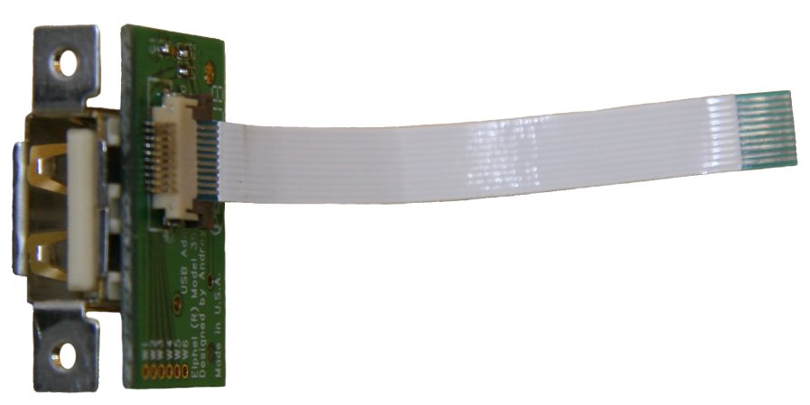
[[Image:103693_sm.jpeg|frame|[[Media:103693.jpeg|103693: External USB connector adapter board]]]] | [[Image:103693_sm.jpeg|frame|[[Media:103693.jpeg|103693: External USB connector adapter board]]]] | ||
| + | === Features === | ||
10369 interface board is an extension board for the [[353|Elphel 353/363 series cameras]]. | 10369 interface board is an extension board for the [[353|Elphel 353/363 series cameras]]. | ||
* It provides multiple interfaces and peripherals to the camera: | * It provides multiple interfaces and peripherals to the camera: | ||
| Line 19: | Line 20: | ||
** Clock/calendar with the super-capacitor backup power | ** Clock/calendar with the super-capacitor backup power | ||
** EEPROM for the board identification and configuration | ** EEPROM for the board identification and configuration | ||
| − | + | === Connectors === | |
---- | ---- | ||
| − | + | ==== J1 - AUX (from the CPU board) ==== | |
{| class="wikitable" style="background:#fcfcfc; " border="1" | {| class="wikitable" style="background:#fcfcfc; " border="1" | ||
|+ AUX connector (from 10353) | |+ AUX connector (from 10353) | ||
| Line 65: | Line 66: | ||
---- | ---- | ||
| − | + | ==== J2 - IDE (from the CPU board) ==== | |
{| class="wikitable" style="background:#fcfcfc; " border="1" | {| class="wikitable" style="background:#fcfcfc; " border="1" | ||
| Line 117: | Line 118: | ||
---- | ---- | ||
| − | + | ==== J3 - Power (from the CPU board) ==== | |
{| class="wikitable" style="background:#fcfcfc; " border="1" | {| class="wikitable" style="background:#fcfcfc; " border="1" | ||
|+ Power connector (from 10353) | |+ Power connector (from 10353) | ||
| Line 133: | Line 134: | ||
---- | ---- | ||
| − | + | ==== J4 - Power (optional - to the next boards) ==== | |
{| class="wikitable" style="background:#fcfcfc; " border="1" | {| class="wikitable" style="background:#fcfcfc; " border="1" | ||
|+ Power connector (optional - to the next boards) | |+ Power connector (optional - to the next boards) | ||
| Line 149: | Line 150: | ||
---- | ---- | ||
| − | + | ==== J5 - Power (optional 3.3V in) ==== | |
{| class="wikitable" style="background:#fcfcfc; " border="1" | {| class="wikitable" style="background:#fcfcfc; " border="1" | ||
|+ Power connector (optional 3.3V in) | |+ Power connector (optional 3.3V in) | ||
| Line 168: | Line 169: | ||
---- | ---- | ||
| − | + | ==== J6 - IDE (to adapter/riser) ==== | |
{| class="wikitable" style="background:#fcfcfc; " border="1" | {| class="wikitable" style="background:#fcfcfc; " border="1" | ||
|+ IDE connector to adpaters/risers (103691, 103692) | |+ IDE connector to adpaters/risers (103691, 103692) | ||
| Line 229: | Line 230: | ||
---- | ---- | ||
| − | + | ==== J7 - SATA ==== | |
{| class="wikitable" style="background:#fcfcfc; " border="1" | {| class="wikitable" style="background:#fcfcfc; " border="1" | ||
|+ SATA 7-pin connector to HDD | |+ SATA 7-pin connector to HDD | ||
| Line 254: | Line 255: | ||
---- | ---- | ||
| − | + | ==== J8 - USB0 (to external) ==== | |
{| class="wikitable" style="background:#fcfcfc; " border="1" | {| class="wikitable" style="background:#fcfcfc; " border="1" | ||
|+ USB to 103693 adapter - external connector | |+ USB to 103693 adapter - external connector | ||
| Line 285: | Line 286: | ||
---- | ---- | ||
| − | + | ==== J9 - USB1 (to internal) ==== | |
{| class="wikitable" style="background:#fcfcfc; " border="1" | {| class="wikitable" style="background:#fcfcfc; " border="1" | ||
|+ USB , i2c, GPIO, 3.3V power to extension boards | |+ USB , i2c, GPIO, 3.3V power to extension boards | ||
| Line 316: | Line 317: | ||
---- | ---- | ||
| − | + | ==== J10 - USB2 (to internal) ==== | |
{| class="wikitable" style="background:#fcfcfc; " border="1" | {| class="wikitable" style="background:#fcfcfc; " border="1" | ||
|+ USB , i2c, GPIO, 3.3V power to extension boards | |+ USB , i2c, GPIO, 3.3V power to extension boards | ||
| Line 347: | Line 348: | ||
---- | ---- | ||
| − | + | ==== J11 - USB4 (to internal) ==== | |
{| class="wikitable" style="background:#fcfcfc; " border="1" | {| class="wikitable" style="background:#fcfcfc; " border="1" | ||
|+ USB , i2c, GPIO, 3.3V power to extension boards | |+ USB , i2c, GPIO, 3.3V power to extension boards | ||
| Line 378: | Line 379: | ||
---- | ---- | ||
| − | + | ==== J12 - SYNC (internal, master) ==== | |
{| class="wikitable" style="background:#fcfcfc; " border="1" | {| class="wikitable" style="background:#fcfcfc; " border="1" | ||
|+ Interboard synchronization I/O, master, bottom contacts | |+ Interboard synchronization I/O, master, bottom contacts | ||
| Line 398: | Line 399: | ||
---- | ---- | ||
| − | + | ==== J13 - SYNC (internal, slave) ==== | |
{| class="wikitable" style="background:#fcfcfc; " border="1" | {| class="wikitable" style="background:#fcfcfc; " border="1" | ||
|+ Interboard synchronization I/O, slave, bottom contacts | |+ Interboard synchronization I/O, slave, bottom contacts | ||
| Line 418: | Line 419: | ||
---- | ---- | ||
| − | + | ==== J14 - SYNC (internal, slave) ==== | |
{| class="wikitable" style="background:#fcfcfc; " border="1" | {| class="wikitable" style="background:#fcfcfc; " border="1" | ||
|+ Interboard synchronization I/O, slave, top contacts | |+ Interboard synchronization I/O, slave, top contacts | ||
| Line 438: | Line 439: | ||
---- | ---- | ||
| − | + | ==== J15 - SYNC (external) ==== | |
{| class="wikitable" style="background:#fcfcfc; " border="1" | {| class="wikitable" style="background:#fcfcfc; " border="1" | ||
|+ Intercamera synchronization I/O, modular RJ-14 | |+ Intercamera synchronization I/O, modular RJ-14 | ||
| Line 458: | Line 459: | ||
---- | ---- | ||
| − | + | ==== J16 - RS-232 ==== | |
{| class="wikitable" style="background:#fcfcfc; " border="1" | {| class="wikitable" style="background:#fcfcfc; " border="1" | ||
|+ Serial RS-232 port, modular RJ-25 | |+ Serial RS-232 port, modular RJ-25 | ||
| Line 481: | Line 482: | ||
---- | ---- | ||
| − | + | ==== J17 - Fan ==== | |
{| class="wikitable" style="background:#fcfcfc; " border="1" | {| class="wikitable" style="background:#fcfcfc; " border="1" | ||
|+ Optional Fan connection (3.3V/5.0V) | |+ Optional Fan connection (3.3V/5.0V) | ||
| Line 497: | Line 498: | ||
---- | ---- | ||
| − | + | ==== W2-W4 - Terminals for external temperature sensor ==== | |
{| class="wikitable" style="background:#fcfcfc; " border="1" | {| class="wikitable" style="background:#fcfcfc; " border="1" | ||
|+ Solder terminals for optional thermal sensor | |+ Solder terminals for optional thermal sensor | ||
Revision as of 10:47, 26 June 2008
Contents
- 1 10369
- 1.1 Features
- 1.2 Connectors
- 1.2.1 J1 - AUX (from the CPU board)
- 1.2.2 J2 - IDE (from the CPU board)
- 1.2.3 J3 - Power (from the CPU board)
- 1.2.4 J4 - Power (optional - to the next boards)
- 1.2.5 J5 - Power (optional 3.3V in)
- 1.2.6 J6 - IDE (to adapter/riser)
- 1.2.7 J7 - SATA
- 1.2.8 J8 - USB0 (to external)
- 1.2.9 J9 - USB1 (to internal)
- 1.2.10 J10 - USB2 (to internal)
- 1.2.11 J11 - USB4 (to internal)
- 1.2.12 J12 - SYNC (internal, master)
- 1.2.13 J13 - SYNC (internal, slave)
- 1.2.14 J14 - SYNC (internal, slave)
- 1.2.15 J15 - SYNC (external)
- 1.2.16 J16 - RS-232
- 1.2.17 J17 - Fan
- 1.2.18 W2-W4 - Terminals for external temperature sensor
10369


Features
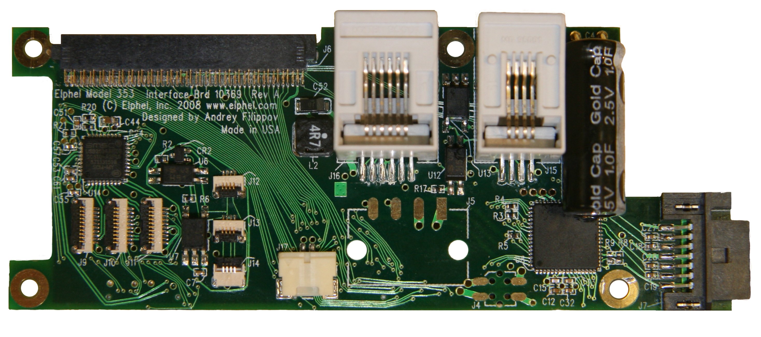
10369 interface board is an extension board for the Elphel 353/363 series cameras.
- It provides multiple interfaces and peripherals to the camera:
- SATA port for external disk drives
- Compact Flash (in "True IDE" mode) and IDE HDD ports (with adapter/riser boards: 103691, 103692)
- RS-232 port
- Opto-isolated I/O port for synchronizing the camera or synchronizing together multiple cameras (modular RJ14 external connector)
- Opto-isolated I/O port for synchronizing multiple camera modules in the same enclosure (flex cable connectors)
- Digital thermometer with internal ("system") and external thermal sensor (emitter-base junction of PNP or NPN transistor)
- Fan driver, controlled by the digital thermometer with programmable on/off temperature
- Clock/calendar with the super-capacitor backup power
- EEPROM for the board identification and configuration
Connectors
J1 - AUX (from the CPU board)
| Pin | Signal | Notes | Pin | Signal | Notes | |
|---|---|---|---|---|---|---|
| 1 | GND | 2 | GND | |||
| 3 | EXT[0] | GPIO | 4 | EXT[2] | GPIO | |
| 5 | EXT[1] | GPIO | 6 | EXT[3] | GPIO | |
| 7 | GND | 8 | GND | |||
| 9 | EXT[4] | GPIO | 10 | EXT[6] | GPIO | |
| 11 | EXT[5] | GPIO | 12 | EXT[7] | GPIO | |
| 13 | GND | 14 | GND | |||
| 15 | EXT[8] | GPIO | 16 | EXT[10] | GPIO | |
| 17 | EXT[9] | GPIO | 18 | EXT[11] | GPIO | |
| 19 | GND | 20 | GND | |||
| 21 | CTS | RS232 | 22 | RTS | RS232 | |
| 23 | RXD | RS232 | 24 | TXD | RS232 | |
| 25 | VP33 | +3.3V | 26 | VP33 | +3.3V | |
| 27 | U0VM | USB | 28 | U0VP | USB | |
| 29 | VP33 | +3.3V | 30 | VP33 | +3.3V |
J2 - IDE (from the CPU board)
| Pin | Signal | Notes | Pin | Signal | Notes | |
|---|---|---|---|---|---|---|
| 1 | IDE_RST | 2 | GND | |||
| 3 | IDE_D[7] | 4 | IDE_D[8] | |||
| 5 | IDE_D[6] | 6 | IDE_D[9] | |||
| 7 | IDE_D[5] | 8 | IDE_D[10] | |||
| 9 | IDE_D[4] | 10 | IDE_D[11] | |||
| 11 | IDE_D[3] | 12 | IDE_D[12] | |||
| 13 | IDE_D[2] | 14 | IDE_D[13] | |||
| 15 | IDE_D[1] | 16 | IDE_D[14] | |||
| 17 | IDE_D[0] | 18 | IDE_D[15] | |||
| 19 | GND | 20 | GND | |||
| 21 | IDE_DMARQ | 22 | GND | |||
| 23 | IDE_IOW | 24 | GND | |||
| 25 | IDE_IOR | 26 | GND | |||
| 27 | IDE_IORDY | 28 | GND | |||
| 29 | IDE_DMACK | 30 | GND | |||
| 31 | IDE_INTRQ | 32 | EXT_OE | not used | ||
| 33 | IDE_A[1] | 34 | -- | |||
| 35 | IDE_A[0] | 36 | IDE_A[2] | |||
| 37 | IDE_CS0 | 38 | IDE_CS1 | |||
| 39 | -- | 40 | GND |
J3 - Power (from the CPU board)
| Pin | Signal | Notes | Pin | Signal | Notes | |
|---|---|---|---|---|---|---|
| 1 | GND | 3 | VP33 | +3.3V | ||
| 2 | LPWR48M | -48V, isolated, primary | 4 | LPWR48P | +48V, isolated, primary |
Note: +/- 48V are non-regulated input power rails. For 12V or 24V camera modifications these lines will also have +/-12V or +/-24V.
J4 - Power (optional - to the next boards)
| Pin | Signal | Notes | Pin | Signal | Notes | |
|---|---|---|---|---|---|---|
| 1 | GND | 3 | VP33 | +3.3V | ||
| 2 | LPWR48M | -48V, isolated, primary | 4 | LPWR48P | +48V, isolated, primary |
Note: J4 is normally not installed. It is used in some camera modificatios where ther is another board on top of the 10369 that needs power - J4 is located oppposite to J3, same as on 10353 system board.
J5 - Power (optional 3.3V in)
| Pin | Signal | Notes |
|---|---|---|
| 1 | GND | |
| 2 | VP33 | +3.3V |
| 3 | LPWR48M | -48V, isolated, primary |
| 4 | LPWR48P | +48V, isolated, primary |
Note: J5 is normally not installed. It may be used in multi-camera systems to provide 3.3V from the commomn to all camera modules power supply (DC-DC converter on 10353 should not be installed).
J6 - IDE (to adapter/riser)
| Pin | Signal | Notes | Pin | Signal | Notes | |
|---|---|---|---|---|---|---|
| 1 | CF1PRESENT | GND if CF1 installed | 2 | GND | ||
| 3 | IDE_D[11] | 4 | IDE_D[3] | |||
| 5 | IDE_D[12] | 6 | IDE_D[4] | |||
| 7 | IDE_D[13] | 8 | IDE_D[5] | |||
| 9 | IDE_D[14] | 10 | IDE_D[6] | |||
| 11 | IDE_D[15] | 12 | IDE_D[7] | |||
| 13 | IDE_CS1 | 14 | IDE_CS0 | |||
| 15 | -- | 16 | -- | |||
| 17 | IDE_IOR | 18 | GND | |||
| 19 | IDE_IOW | 20 | -- | |||
| 21 | -- | 22 | -- | |||
| 23 | IDE_INTRQ | 24 | -- | |||
| 25 | +3.3V | 26 | +3.3V | |||
| 27 | GND | 28 | EXT[0](SCL) | |||
| 29 | RST_CFS | Reset master | 30 | EXT[0](SDA) | ||
| 31 | RST_CFM | Reset slave | 32 | IDE_A[2] | ||
| 33 | IDE_IORDY | 34 | -- | |||
| 35 | IDE_DMARQ | 36 | IDE_A[2] | |||
| 37 | IDE_DMACK | 38 | IDE_A[1] | |||
| 39 | IDE_DASP | 40 | IDE_A[0] | |||
| 41 | IDE_PDIAG | 42 | IDE_D[0] | |||
| 43 | IDE_D[8] | 44 | IDE_D[1] | |||
| 45 | IDE_D[9] | 46 | IDE_D[2] | |||
| 47 | IDE_D[10] | 48 | -- | |||
| 49 | GND | 50 | CF0PRESENT | GND if CF0 installed |
J7 - SATA
| Pin | Signal | Notes |
|---|---|---|
| 1 | GND | |
| 2 | SATATP | Transmit + |
| 3 | SATATM | Transmit - |
| 4 | GND | |
| 5 | SATARM | Receive - |
| 6 | SATARP | Receive + |
| 7 | GND |
J8 - USB0 (to external)
| Pin | Signal | Notes |
|---|---|---|
| 1 | GND | System ground, needs series inductor (on 103693) |
| 2 | DP1 | USB data + |
| 3 | DM1 | USB data - |
| 4 | PW1 | USB +5V power (switched) |
| 5 | GND | |
| 6 | EXT[0] | i2c SCL |
| 7 | EXT[1] | i2c SDA |
| 8 | EXT[6] | GPIO |
| 9 | EXT[7] | GPIO |
| 10 | P3_1 | +3.3V power |
J9 - USB1 (to internal)
| Pin | Signal | Notes |
|---|---|---|
| 1 | GND | |
| 2 | DP2 | USB data + |
| 3 | DM2 | USB data - |
| 4 | PW2 | USB +5V power (switched) |
| 5 | GND | |
| 6 | EXT[0] | i2c SCL |
| 7 | EXT[1] | i2c SDA |
| 8 | EXT[2] | GPIO |
| 9 | EXT[3] | GPIO |
| 10 | P3_2 | +3.3V power |
J10 - USB2 (to internal)
| Pin | Signal | Notes |
|---|---|---|
| 1 | GND | |
| 2 | DP3 | USB data + |
| 3 | DM3 | USB data - |
| 4 | PW3 | USB +5V power (switched) |
| 5 | GND | |
| 6 | EXT[0] | i2c SCL |
| 7 | EXT[1] | i2c SDA |
| 8 | EXT[4] | GPIO |
| 9 | EXT[5] | GPIO |
| 10 | P3_3 | +3.3V power |
J11 - USB4 (to internal)
| Pin | Signal | Notes |
|---|---|---|
| 1 | GND | |
| 2 | DP4 | USB data + |
| 3 | DM5 | USB data - |
| 4 | PW4 | USB +5V power (switched) |
| 5 | GND | |
| 6 | EXT[0] | i2c SCL |
| 7 | EXT[1] | i2c SDA |
| 8 | EXT[6] | GPIO |
| 9 | EXT[7] | GPIO |
| 10 | P3_4 | +3.3V power |
J12 - SYNC (internal, master)
| Pin | Signal | Notes |
|---|---|---|
| 1 | GND | Driver return |
| 2 | ISYNCDR | Driver output |
| 3 | ISYNC1 | Optoisolated I/O |
| 4 | ISYNC2 | Optoisolated I/O return |
Note: Connect J12 to J14 on the next camera in chain with a 4-conductor flex jumper, then from J13 of that next camera to the next in chain's J14, and so on. J12 and J13 have contacts on the bottom side, J14 - on the top to simplify chaining.
J13 - SYNC (internal, slave)
| Pin | Signal | Notes |
|---|---|---|
| 1 | ISYNC2 | Optoisolated I/O return |
| 2 | ISYNC1 | Optoisolated I/O |
| 3 | ISYNC1 | Optoisolated I/O |
| 4 | ISYNC2 | Optoisolated I/O return |
Note: Connect J12 to J14 of the next camera module in chain.
J14 - SYNC (internal, slave)
| Pin | Signal | Notes |
|---|---|---|
| 1 | ISYNC2 | Optoisolated I/O return |
| 2 | ISYNC1 | Optoisolated I/O |
| 3 | ISYNC1 | Optoisolated I/O |
| 4 | ISYNC2 | Optoisolated I/O return |
Note: Connect J14 to J13 of the previous camera module in chain (if the previous is not the master). If it is the master, connect J14 to the master's J12 instead of the J13
J15 - SYNC (external)
| Pin | Signal | Notes |
|---|---|---|
| 1 | GND | Driver return |
| 2 | XSYNC1 | Optoisolated I/O |
| 3 | XISYNC2 | Optoisolated I/O return |
| 4 | XSYNCDR | Driver output |
Note: In order to synchronize multiple cameras connect the pins 2 on all cameras together, same for all the pins 3. Additionally connect pin 1 on the 'master' (synchronization source) camera to pin 3, pin 4 - with pin2.
J16 - RS-232
| Pin | Signal | Notes |
|---|---|---|
| 1 | XCTS | CTS |
| 2 | XRXD | RxD |
| 3 | GND | |
| 4 | GND | |
| 5 | XTXD | TxD |
| 6 | XRTS | RTS |
J17 - Fan
| Pin | Signal | Notes |
|---|---|---|
| 1 | FANPOS | Fan positive terminal |
| 2 | GND | Fan negative terminal |
Note: Default configuration supports 3.3VDC fans, in order to switch to 5.0V you need to open (cut trace) jumper JP2 and close (solder together terminals of) jumper JP1.
W2-W4 - Terminals for external temperature sensor
| Pin | Signal | Notes |
|---|---|---|
| W2 | TSNSP | Thermal sensor positive |
| W3 | TSNSP | Thermal sensor positive |
| W3 | GND | connect to sensor cable shield |
Note: small NPN (i.e. 2N3904) or PNP (i.e. 2N3906) can be used as an external sensor. Connect NPN base (or PNP emitter) to W2, NPN emitter (or PNP base) to W3 (W4 may be connected to the shield around these two wires that shoul be twisted). If no sensor is used W2 and W3 should be connected together to enable fan control.