Difference between revisions of "Test Tasks"
m |
|||
| Line 7: | Line 7: | ||
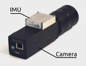
|valign='top'|[[File:NC353L-369-IMU-GPS 4 comments.jpeg|300px|thumb|IMU, ADIS16375 in NC353L-369 camera]] | |valign='top'|[[File:NC353L-369-IMU-GPS 4 comments.jpeg|300px|thumb|IMU, ADIS16375 in NC353L-369 camera]] | ||
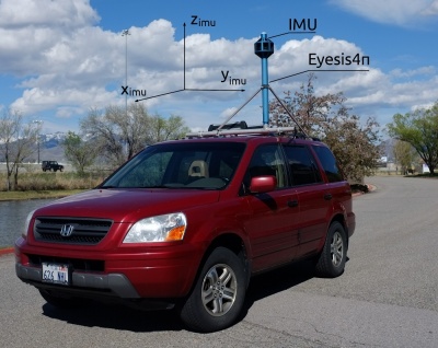
|[[File:Eyesis4pi imu axes3.jpeg|400px|thumb|IMU in Eyesis4π]] | |[[File:Eyesis4pi imu axes3.jpeg|400px|thumb|IMU in Eyesis4π]] | ||
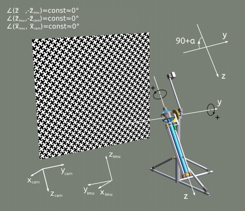
| + | |[[File:Eyesis-with-cradle-pattern_small_2.jpeg|500px|thumb|Positive rotation angles in the calibration machine]] | ||
|} | |} | ||
Revision as of 16:49, 13 September 2012
Contents
Area: IMU Data Processing
About
"An Inertial Measurement Unit (IMU) is an electronic device that measures and reports on a craft's velocity, orientation, and gravitational forces, using a combination of accelerometers and gyroscopes, sometimes also magnetometers..." © Wikipedia
We use ADIS16375 (fully compatible with ADIS16488) with a tri-axis gyroscope and a tri-axis accelerometer.
Our projects
1. Images Relative Orientation
The goal is to find how the camera rotated/moved (Rotation Matrix) between the shots. Knowing the images' relative orientation allows to use this information for further 3D reconstruction.
2. ERS Correction
Our sensor is Aptina's MT9P006 - CMOS, 5MP, 1/2.5". It has an ERS (Electronic Rolling Shutter) - the image scan time is about 1/15 s (~66 ms) while IMU samples data at 2.460 kHz (T = 0.406 ms) which makes it possible to reconstruct how the camera moved during the image acquisition and correct the ERS effect by placing each pixel according to the sensor orientation at each moment of time. This only corrects the movement/rotation of the camera but not the ERS from the moving objects.


