Difference between revisions of "10344"
From ElphelWiki
| Line 1: | Line 1: | ||
==10344== | ==10344== | ||
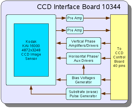
[[Image:10344bd.png|frame|[[Media:10344asch.pdf|10344 Circuit Diagram]]]] | [[Image:10344bd.png|frame|[[Media:10344asch.pdf|10344 Circuit Diagram]]]] | ||
| − | 10344 CCD Interface Board is designed to work together with the CCD Control Board (10347), both controlled by the [[10353|10353 processor board]]. This board is built around 16 Megapixel interline Kodak KAI-16000 CCD image sensor. | + | 10344 CCD Interface Board is a part of [[353|Elplhel Model 353/363 Camera]]. It is designed to work together with the CCD Control Board (10347), both controlled by the [[10353|10353 processor board]]. This board is built around 16 Megapixel interline Kodak KAI-16000 CCD image sensor. |
This board include: | This board include: | ||
* pin sockets for the KAI-16000 CCD image sensor (to facilitate sensor replacement) | * pin sockets for the KAI-16000 CCD image sensor (to facilitate sensor replacement) | ||
Revision as of 06:56, 11 April 2007
10344
10344 CCD Interface Board is a part of Elplhel Model 353/363 Camera. It is designed to work together with the CCD Control Board (10347), both controlled by the 10353 processor board. This board is built around 16 Megapixel interline Kodak KAI-16000 CCD image sensor. This board include:
- pin sockets for the KAI-16000 CCD image sensor (to facilitate sensor replacement)
- a pair of pre-amplifiers of the CCD output signals
- high-current amplifiers for CCD vertical phase drivers. These signals are multi-level, they are generated by a DAC on the 10347 board and then amplified on this board.
- fast high-current drivers for horizontal phase signals - the AC component is generated by the switches with regulated input voltage, DC shift is added to it (for some signals - to the high level, for others - to the lower level) by the programmable bias voltage generator
- bias voltage generator is used to provide DC bias for horizontal phase signals and the levels for DC signals required fro CCD operation. It uses multi-channel serial DAC (programmed by the signals generated by the FPGA on the 10347 board and operational amplifiers to provide required output voltage range for each signal.
- substrate (erase) pulse generator provides a high voltage (>40V) pulse to erase pixels before the exposure
Connectors:
- 10344 board has a single 40-pin connector (J5) in the middle of the board that links it to the 10347 board
