10347
From ElphelWiki
10347


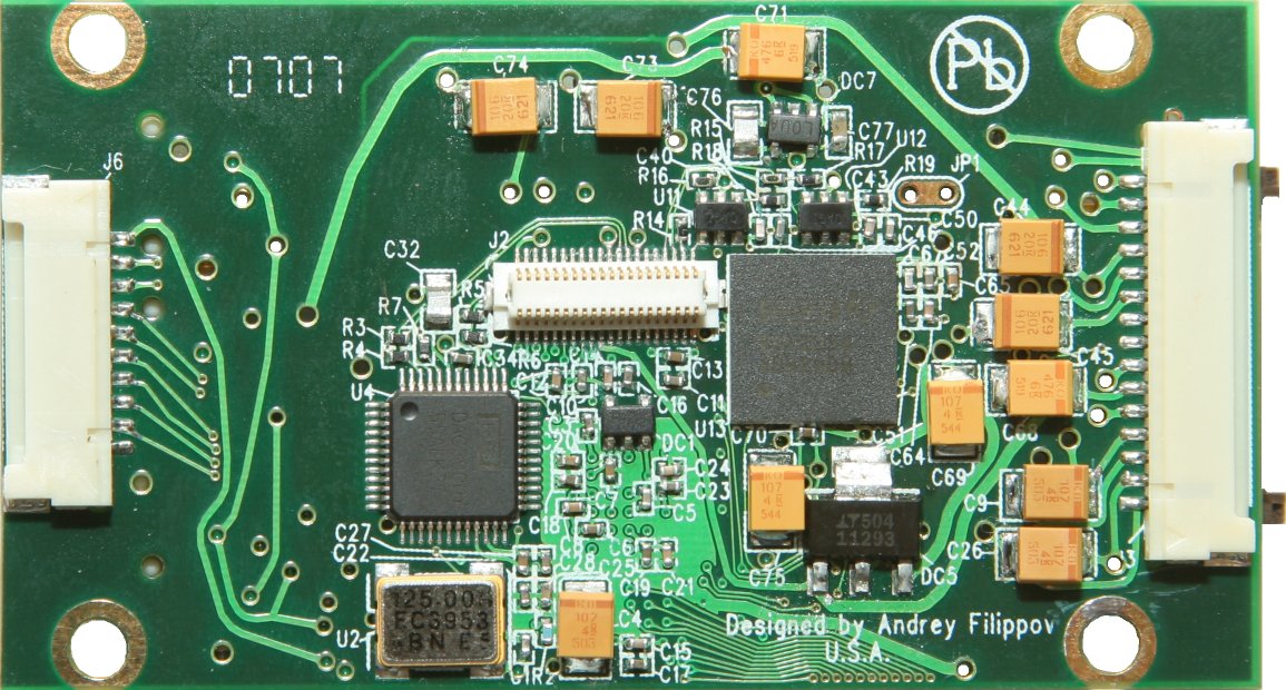
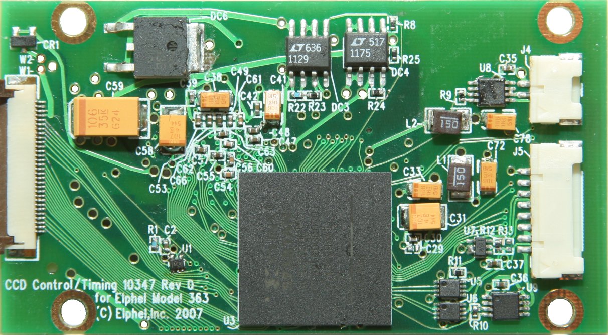
10347 is a half of a two-board stack (the second board can currently be one of the two - 10342 and 10344) designed to use 35mm format Kodak CCDs in Elphel Model 363 camera (that uses the same 10353 Processor Board as the Model 353 cameras). The sensor-related circuitry was split into two boards for the following reasons:
- to reduce the overall footprint of the boards to simplify muti-sensor applications. Current stack width just slightly exceeds sensor width
- to simplify accommodation of similar sensors - only one of the boards in a stack needs to be replaced when switching to a different sensor
- The 10347 board includes FPGA (same Xilinx Spartan 3e 1200K gates as in the 10353, 10357 and 10359 boards). Similar to 10359 board 10347 has just 1 signal overhead for JTAG configuration of the FPGA. All the other signals needed to program FPGA are shared with the data lines. This FPGA is used to:
- control the analog circuitry - most of the voltage biases and signal amplitudes are controled by the software through the on-board DACs;
- provide the timing for all the signals required for the CCD and ADC operation
- interface to the 10535 (Processor) board
- buffer and combine signals from the 2 sensor outputs into a single progressive digital video output
- provide correction to pixel values (bias, gain) individually for each color component and (in some applications) depending on the pixel position on the sensor.
- Dual-channel 14-bit ADC is used to digitize the signals from two CCD outputs,
- Differential amplifiers simplify transferring analog signals from the sensor interface board and reference the video signals to the ADC analog ground.
- Dual-channel 10-bit DAC generates multi-level signals that (after being amplified on the sensor interface board) drive high-capacitance CCD vertical phases. Faster bi-level horizontal phase signals are generated by the switches on the CCD interface board using LVTTL signals from the FPGA.
- Linear voltage regulators clean up power supply voltages received from the switching power supply and provide power for the ADC, amplifiers and for the CCD interface board.
- Lens control module provides power and serial interface signals to some standard 35-mm format lenses
- Fan driver provides interface to an optional 5V cooling fan
Connectors:
- 30-conductor flex cable connector (J1) is used to communicate with the 10353 (Processor) board or optional 10359 Mupliplexor board
- 15-pin connector (J7) provides power that is used on the 10347 board itself, sensor interface board (10342/10344) and additional attached devices
- 10-pin connector (J6) provides 8 LVTTL signals for an optional shutter control board together with 3.3V power
- 8-pin connector (J5) provides power and serial control signals for the standard motorized lenses.
- 2-pin connector (J4) is used to connect an optional cooling fan.