Difference between revisions of "Checking voltage levels on 10353"
| Line 15: | Line 15: | ||
Image:C84-probe.jpeg|C84 output should be 2.5v. C84 provide filtered power to the sensor, to the FPGA dedicated memory and two of the FPGA banks. | Image:C84-probe.jpeg|C84 output should be 2.5v. C84 provide filtered power to the sensor, to the FPGA dedicated memory and two of the FPGA banks. | ||
Image:C86-probe.jpeg|C86 output should be 1.5v. C86 provide filtered power to the Etrax FS CPU core. | Image:C86-probe.jpeg|C86 output should be 1.5v. C86 provide filtered power to the Etrax FS CPU core. | ||
| − | Image:C88-probe.jpeg|C88 output should be 1.2v. | + | Image:C88-probe.jpeg|C88 output should be 1.2v. C88 provide filtered power to to the FPGA core. |
</gallery> | </gallery> | ||
Latest revision as of 12:25, 20 May 2009
The camera need to be provided with regulated 3.3v power source.
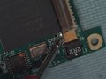
If the DC/DC is installed, the right part of the J4 connector is the input and the left part is 3.3v output.
If the DC/DC is not installed the left part may be used as input for regulated 3.3v power source.
Internally the different camera components use 3.3v, 2.5v, 1,5v and 1.2v.

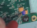
It is easy to check these voltage levels. Just connect ground to the network jack and probe capacitors C84, C86 & C88
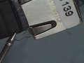
ground
C84 output should be 2.5v. C84 provide filtered power to the sensor, to the FPGA dedicated memory and two of the FPGA banks.
C86 output should be 1.5v. C86 provide filtered power to the Etrax FS CPU core.
C88 output should be 1.2v. C88 provide filtered power to to the FPGA core.


Voltages should be stable and correspond to the specified values +/-2%
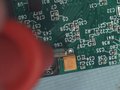
Here is an example of a damaged 10353 board, first I did noticed 0.8v instead of 1.2v on C88.
That's why the board was not able to program the FPGA. A more careful look on the board revealed that components C3, C16, C20 & R40 are missing.
