Difference between revisions of "Eyesis assembly"
From ElphelWiki
| (2 intermediate revisions by the same user not shown) | |||
| Line 1: | Line 1: | ||
| − | ===Step 1: Front Ends=== | + | == Head == |
| + | |||
| + | === Step 1: Head + Front Ends (already assembled and focused)<br> === | ||
| + | |||
{| | {| | ||
| − | |[[Image:Eyesis sfe parts.jpeg | + | |- |
| − | |[[Image:Eyesis sfe assembled.jpeg | + | | [[Image:Eyesis sfe parts.jpeg|thumb|300px]] |
| + | | [[Image:Eyesis sfe assembled.jpeg|thumb|500px]] | ||
|} | |} | ||
| − | + | ||
| − | + | *Connect cables to the Front Ends. | |
| − | ===Step | + | *Put the front ends one by one into the head. |
| − | * See Fig.1. There are 3 holes in the disk attached to the head bottom. The 1st hole is on the above of one of the 'eyes' and others are not - so it's easy to find it. | + | |
| − | * See Fig.2. Attach the part with main boards to the head (use thread-locker with these 3 screws). The cables from the marked sensors will go to the closest to the 1st hole board (on Fig.1,2 colors and eyes match) | + | === Step 2: Head + Boards === |
| − | * Rotate the head counter clockwise (from 'hole 1' to 'hole 2') - attach the next 3 cables. | + | |
| − | * Remaining 3 cables go to the board near the 3rd hole. | + | *See Fig.1. There are 3 holes in the disk attached to the head bottom. The 1st hole is on the above of one of the 'eyes' and others are not - so it's easy to find it. |
| + | *See Fig.2. Attach the part with main boards to the head (use thread-locker with these 3 screws). The cables from the marked sensors will go to the closest to the 1st hole board (on Fig.1,2 colors and eyes match) | ||
| + | *Rotate the head counter clockwise (from 'hole 1' to 'hole 2') - attach the next 3 cables. | ||
| + | *Remaining 3 cables go to the board near the 3rd hole. | ||
{| | {| | ||
| − | |[[Image:Head boards 1.jpeg | + | |- |
| − | |[[Image:Head boards 2.jpeg | + | | [[Image:Head boards 1.jpeg|thumb|400px]] |
| + | | [[Image:Head boards 2.jpeg|thumb|350px]] | ||
|} | |} | ||
| − | * Attach sync cables to the 10369 boards: | + | *Attach sync cables to the 10369 boards: |
| + | |||
Notes: | Notes: | ||
* The 1st board is the one near the 1st hole. | * The 1st board is the one near the 1st hole. | ||
| Line 25: | Line 34: | ||
{| | {| | ||
| − | |[[Image:Sync cables.jpg | + | |- |
| + | | [[Image:Sync cables.jpg|thumb|400px]] | ||
|} | |} | ||
| + | |||
| + | == Box == | ||
| + | |||
| + | {a schematic picture + photo}<br> | ||
| + | |||
| + | == Eyesis == | ||
| + | |||
| + | #Put a "cup" on the pole. | ||
| + | #Connect the corresponding cables from the box (coming out of the pole) to the head {add a photo with comments} | ||
| + | #Attach the head to the cup. | ||
| + | #Choose the head orientation and tighten the "cup"'s 2 big screws. | ||
Latest revision as of 19:28, 30 November 2010
Contents
[hide]Head
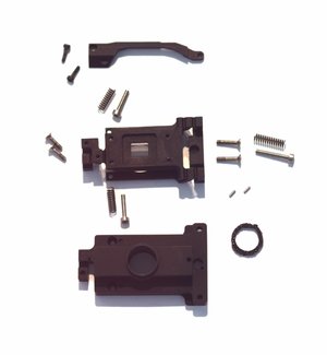
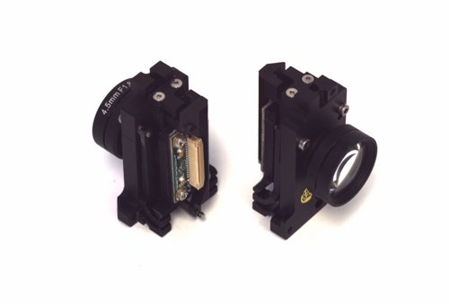
Step 1: Head + Front Ends (already assembled and focused)
- Connect cables to the Front Ends.
- Put the front ends one by one into the head.
Step 2: Head + Boards
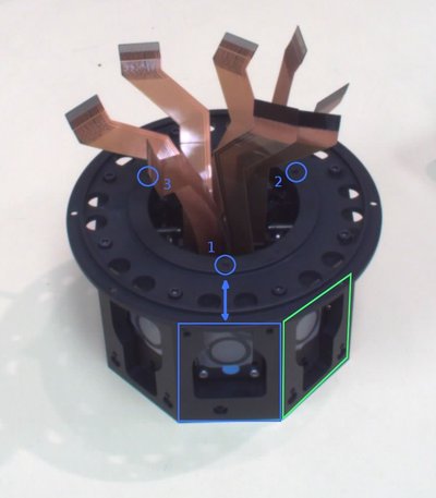
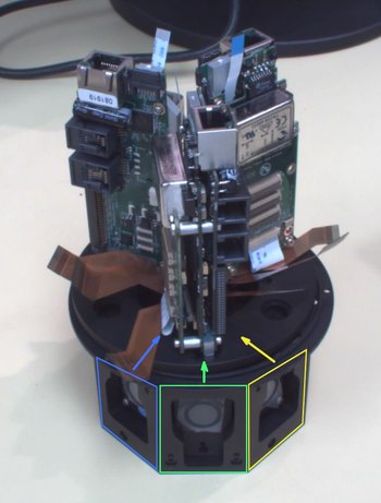
- See Fig.1. There are 3 holes in the disk attached to the head bottom. The 1st hole is on the above of one of the 'eyes' and others are not - so it's easy to find it.
- See Fig.2. Attach the part with main boards to the head (use thread-locker with these 3 screws). The cables from the marked sensors will go to the closest to the 1st hole board (on Fig.1,2 colors and eyes match)
- Rotate the head counter clockwise (from 'hole 1' to 'hole 2') - attach the next 3 cables.
- Remaining 3 cables go to the board near the 3rd hole.
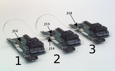
- Attach sync cables to the 10369 boards:
Notes:
 * The 1st board is the one near the 1st hole.
 * J14 - cable foil up
 * J12, J13 - cable foil down
 * Better to start connecting with J14 side of the cable.
Box
{a schematic picture + photo}
Eyesis
- Put a "cup" on the pole.
- Connect the corresponding cables from the box (coming out of the pole) to the head {add a photo with comments}
- Attach the head to the cup.
- Choose the head orientation and tighten the "cup"'s 2 big screws.
