Difference between revisions of "Eyesis assembly"
From ElphelWiki
| Line 1: | Line 1: | ||
===Step 1: Front Ends=== | ===Step 1: Front Ends=== | ||
| + | {| | ||
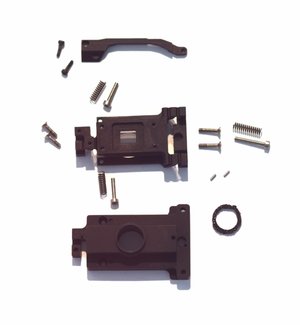
| + | |[[Image:Eyesis sfe parts.jpeg|300px|thumb|Fig.1 Metal parts for an Eyesis Sensor Front End (ESFE)]] | ||
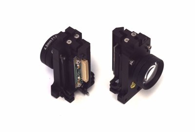
| + | |[[Image:Eyesis sfe assembled.jpeg|400px|thumb|Fig.2 Assembled ESFE]] | ||
| + | |} | ||
===Step 2: Head=== | ===Step 2: Head=== | ||
===Step 3: Attaching camera boards=== | ===Step 3: Attaching camera boards=== | ||
| Line 9: | Line 13: | ||
{| | {| | ||
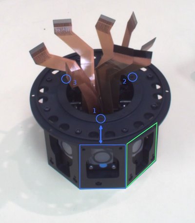
| − | |[[Image:Head boards 1.jpeg|400px|thumb|Fig. | + | |[[Image:Head boards 1.jpeg|400px|thumb|Fig.3 Head]] |
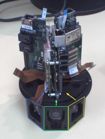
| − | |[[Image:Head boards 2.jpeg|350px|thumb|Fig. | + | |[[Image:Head boards 2.jpeg|350px|thumb|Fig.4 Head + Boards]] |
|} | |} | ||
| Line 21: | Line 25: | ||
{| | {| | ||
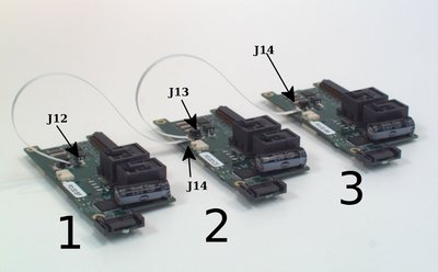
| − | |[[Image:Sync cables.jpg|400px|thumb|Fig. | + | |[[Image:Sync cables.jpg|400px|thumb|Fig.5 Sync cables connection scheme]] |
|} | |} | ||
Revision as of 09:28, 22 June 2010
Contents
Step 1: Front Ends
Step 2: Head
Step 3: Attaching camera boards
Step 4: Head + Boards
- See Fig.1. There are 3 holes in the disk attached to the head bottom. The 1st hole is on the above of one of the 'eyes' and others are not - so it's easy to find it.
- See Fig.2. Attach the part with main boards to the head (use thread-locker with these 3 screws). The cables from the marked sensors will go to the closest to the 1st hole board (on Fig.1,2 colors and eyes match)
- Rotate the head counter clockwise (from 'hole 1' to 'hole 2') - attach the next 3 cables.
- Remaining 3 cables go to the board near the 3rd hole.
- Attach sync cables to the 10369 boards:
Notes:
 * The 1st board is the one near the 1st hole.
 * J14 - cable foil up
 * J12, J13 - cable foil down
 * Better to start connecting with J14 side of the cable.
