Difference between revisions of "103693"
From ElphelWiki
| Line 1: | Line 1: | ||
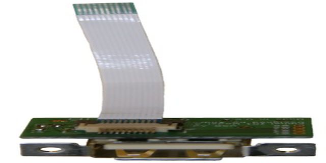
[[Image:103693_md.jpeg|frame|[[Media:103693.pdf|103693 Circuit Diagram, Parts List, PCB layout]] [[Media:103693_gerber.tar.gz|103693 Gerber files]]]] | [[Image:103693_md.jpeg|frame|[[Media:103693.pdf|103693 Circuit Diagram, Parts List, PCB layout]] [[Media:103693_gerber.tar.gz|103693 Gerber files]]]] | ||
| + | |||
| + | 103693 is an adapter board with External USB type A female USB connector s mounted on the back panel of the [[353 | Elphel Model 353 camera]]. It is used with the [[10369]] board. | ||
| + | |||
| + | |||
| + | ---- | ||
| + | |||
| + | ==== J1 - to 10369 board === | ||
| + | {| class="wikitable" style="background:#fcfcfc; " border="1" | ||
| + | |+ USB , i2c, GPIO, 3.3V power from 10369 board | ||
| + | |- | ||
| + | ! Pin !! Signal !! Notes | ||
| + | |- | ||
| + | | 1 || VP33 || +3.3V power | ||
| + | |- | ||
| + | | 2 || AUX1 || GPIO | ||
| + | |- | ||
| + | | 3 || AUX0 || GPIO | ||
| + | |- | ||
| + | | 4 || I2CSDA || | ||
| + | |- | ||
| + | | 5 || I2CSCL || | ||
| + | |- | ||
| + | | 6 || GND || | ||
| + | |- | ||
| + | | 7 || VBUSI || USB +5V power | ||
| + | |- | ||
| + | | 8 || DM || USB data - | ||
| + | |- | ||
| + | | 9 || DP || USB data + | ||
| + | |- | ||
| + | | 10 || GND || | ||
| + | |- | ||
| + | |} | ||
| + | |||
| + | |||
| + | ---- | ||
| + | |||
| + | ==== J2 - USB === | ||
| + | {| class="wikitable" style="background:#fcfcfc; " border="1" | ||
| + | |+ external USB connector | ||
| + | |- | ||
| + | ! Pin !! Signal !! Notes | ||
| + | |- | ||
| + | | 1 || VBUSO || USB +5V power | ||
| + | |- | ||
| + | | 2 || DM || USB data - | ||
| + | |- | ||
| + | | 3 || DP || USB data + | ||
| + | |- | ||
| + | | 4 || GNDL || USB GND | ||
| + | |- | ||
| + | |} | ||
| + | |||
| + | |||
| + | ---- | ||
| + | |||
| + | ==== W1..W6 - solder points === | ||
| + | {| class="wikitable" style="background:#fcfcfc; " border="1" | ||
| + | |+ W1..W6 - solder points for optional connections | ||
| + | |- | ||
| + | ! Pin !! Signal !! Notes | ||
| + | |- | ||
| + | | W1 || VP33 || +3.3V power | ||
| + | |- | ||
| + | | W2 || AUX1 || GPIO | ||
| + | |- | ||
| + | | W3 || AUX0 || GPIO | ||
| + | |- | ||
| + | | W4 || I2CSDA || | ||
| + | |- | ||
| + | | W5 || I2CSCL || | ||
| + | |- | ||
| + | | W6 || GND || | ||
| + | |- | ||
| + | |} | ||
Revision as of 21:35, 29 June 2008
103693 is an adapter board with External USB type A female USB connector s mounted on the back panel of the Elphel Model 353 camera. It is used with the 10369 board.
= J1 - to 10369 board
| Pin | Signal | Notes |
|---|---|---|
| 1 | VP33 | +3.3V power |
| 2 | AUX1 | GPIO |
| 3 | AUX0 | GPIO |
| 4 | I2CSDA | |
| 5 | I2CSCL | |
| 6 | GND | |
| 7 | VBUSI | USB +5V power |
| 8 | DM | USB data - |
| 9 | DP | USB data + |
| 10 | GND |
= J2 - USB
| Pin | Signal | Notes |
|---|---|---|
| 1 | VBUSO | USB +5V power |
| 2 | DM | USB data - |
| 3 | DP | USB data + |
| 4 | GNDL | USB GND |
= W1..W6 - solder points
| Pin | Signal | Notes |
|---|---|---|
| W1 | VP33 | +3.3V power |
| W2 | AUX1 | GPIO |
| W3 | AUX0 | GPIO |
| W4 | I2CSDA | |
| W5 | I2CSCL | |
| W6 | GND |
