Difference between revisions of "Eyesis4Pi Calibration"
From ElphelWiki
(→Links) |
|||
| (3 intermediate revisions by the same user not shown) | |||
| Line 1: | Line 1: | ||
| − | ==IMU== | + | ==Goniometer and IMU== |
{| | {| | ||
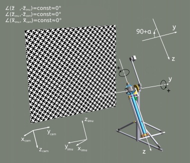
| − | |[[File:Eyesis-with-cradle-pattern_small_2.jpeg| | + | |[[File:Eyesis-with-cradle-pattern_small_2.jpeg|380px|thumb|Fig.1 Positive rotation angles in the calibration machine]] |
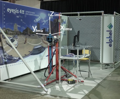
|valign='top'|[[File:Goniometer.jpeg|400px|thumb|Fig.2 Goniometer]] | |valign='top'|[[File:Goniometer.jpeg|400px|thumb|Fig.2 Goniometer]] | ||
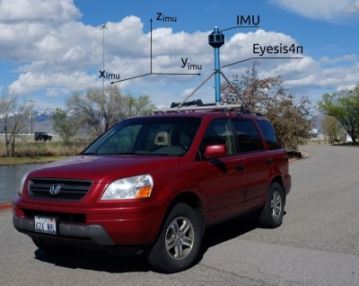
|valign='top'|[[File:Eyesis4pi axes.jpeg|400px|thumb|Fig.3 IMU in Eyesis4π]] | |valign='top'|[[File:Eyesis4pi axes.jpeg|400px|thumb|Fig.3 IMU in Eyesis4π]] | ||
|} | |} | ||
| + | |||
| + | IMU is [http://www.analog.com/en/products/sensors/inertial-measurement-units/adis16375.html ADIS 16375] - 2400 samples per second | ||
During the calibration process the goniometer rotates the camera about 2 axes (y & z on Fig.1) by precisely known angles. To calibrate IMU one needs to match the goniometer angles with the IMU data. | During the calibration process the goniometer rotates the camera about 2 axes (y & z on Fig.1) by precisely known angles. To calibrate IMU one needs to match the goniometer angles with the IMU data. | ||
| Line 29: | Line 31: | ||
* [[Eyesis4pi_Post-Processing|User Guide - Post-processing: ImageJ]] | * [[Eyesis4pi_Post-Processing|User Guide - Post-processing: ImageJ]] | ||
* [[Eyesis4Pi_data_structure|Data Structure Description]] | * [[Eyesis4Pi_data_structure|Data Structure Description]] | ||
| + | * [[Eyesis4Pi_Calibration|Calibration Process]] | ||
| + | [[Category:Eyesis4Pi]] | ||
| + | [[Category:IMU]] | ||
Latest revision as of 11:27, 22 December 2016
Goniometer and IMU
IMU is ADIS 16375 - 2400 samples per second
During the calibration process the goniometer rotates the camera about 2 axes (y & z on Fig.1) by precisely known angles. To calibrate IMU one needs to match the goniometer angles with the IMU data. Notes:
- The images are taken in the middle of the rest state of the goniometer.
- IMU log contains 3 types of events: IMU data packet, GPS data packet, Image captured.
- Images timestamps are recorded in the IMU log.
Calibration process output examples:
Camera 00:0E:64:08:1B:89 IMU calibration data:
- IMU data: test.log-00001...00015
- Goniometer angles: ImageSet_orientation.csv
Axial - angle about the z-axis in degrees (positive rotation is shown on Fig.1)
Tilt - angle about the y-axis in degrees (positive rotation is shown on Fig.1)
- Other goniometer and camera parameters: Camera_parameters.csv
Links
- Code for parsing IMU log: PHP , Java.
- Eyesis4Pi Main Article
- Workflow
- User Guide - Recording
- User Guide - Post-Processing: Footage Procedures
- User Guide - Post-processing: ImageJ
- Data Structure Description
- Calibration Process


