Difference between revisions of "Using 10359 mux with 10393"
From ElphelWiki
| Line 10: | Line 10: | ||
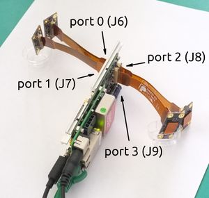
[[File:10393 ports.jpeg|300px|thumb|Fig.1 10393 ports]] | [[File:10393 ports.jpeg|300px|thumb|Fig.1 10393 ports]] | ||
| + | * cable sides as described [[10359#Connect_10353.2C_10359_and_sensors|here]] | ||
* a mux board can be connected to any sensor port | * a mux board can be connected to any sensor port | ||
* up to 4x mux boards at the same time (2- do not require extra power modifications) | * up to 4x mux boards at the same time (2- do not require extra power modifications) | ||
| Line 51: | Line 52: | ||
root@elphel393:~# sync | root@elphel393:~# sync | ||
root@elphel393:~# reboot -f | root@elphel393:~# reboot -f | ||
| + | |||
| + | ===Phase adjustments=== | ||
| + | * For each port with incorrect sensor phase (just a quick link): | ||
| + | http://192.168.0.9/parsedit.php?sensor_port=0&TESTSENSOR&SENSOR_PHASE&MULTI_PHASE1&MULTI_PHASE2&MULTI_PHASE3 | ||
| + | |||
| + | TESTSENSOR - test pattern mode | ||
| + | SENSOR_PHASE - mux or single sensor phase | ||
| + | MULTI_PHASE1 - mux port 0 (J2) | ||
| + | MULTI_PHASE2 - mux port 1 (J3) | ||
| + | MULTI_PHASE3 - mux port 2 (J4) | ||
| + | |||
| + | ** inspect image | ||
| + | ** TESTSENSOR=0x10008 - color bars mode | ||
| + | ** | ||
Revision as of 12:21, 15 November 2017
Contents
Setup
Firmware image
20171115 or apps-autocampars version at least 1.0.46
root@elphel393:~# cat /etc/elphel393/packages/apps-autocampars
1.0.46
Connection
- cable sides as described here
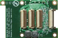
- a mux board can be connected to any sensor port
- up to 4x mux boards at the same time (2- do not require extra power modifications)
- sensor boards can be connected to any unused ports
- if the number of connected mux boards is 3+ then extra power is needed:
quick mod: see Fig.2
lift pins 3,4 on J1, put teflon tape under them and solder a wire to those lifted pins connected. Then add a MOS transistor or a switch that will apply external 3.3 V to W2 when those J1.3, J1.4 have
power.
Modified device tree
Download and use this devicetree.dtb. The easiest way is to overwrite the device tree on the BOOT partition of a recovery SD card and then boot from it.
Application mask (assuming 10389 is not connected)
Without the 10389 the application mode is set in /etc/elphel393/default_10389.xml
root@elphel393:~# cat /etc/elphel393/default_10389.xml
<?xml version="1.0" standalone="yes"?>
<board>
        <model>10389 not present</model>
        <rev>B</rev>
        <serial>F80000</serial>
        <app>MT9P006</app>
        <mode>15</mode>
</board>
To edit on the camera, use nano:
ssh root@192.168.0.9
root@elphel393:~# nano /etc/elphel393/default_10389.xml
To enable programming mux board(s) - set corresponding bits in [19:16]=0x?, [15:0]=0x7777 - then convert to decimal. Examples:
- mux on port 0 (bit 16):
<mode>96119</mode> (=0x17777)
- mux on port 3 (bit 19):
<mode>554871</mode> (=0x87777)
- 2 mux boards on port 1 & 2:
<mode>423799</mode> (=0x67777)
Then
root@elphel393:~# sync
root@elphel393:~# reboot -f
Phase adjustments
- For each port with incorrect sensor phase (just a quick link):
http://192.168.0.9/parsedit.php?sensor_port=0&TESTSENSOR&SENSOR_PHASE&MULTI_PHASE1&MULTI_PHASE2&MULTI_PHASE3
TESTSENSOR - test pattern mode
SENSOR_PHASE - mux or single sensor phase
MULTI_PHASE1 - mux port 0 (J2)
MULTI_PHASE2 - mux port 1 (J3)
MULTI_PHASE3 - mux port 2 (J4)
- inspect image
- TESTSENSOR=0x10008 - color bars mode
Comments
device tree
- decompile device tree
~$ dtc -I dtb -O dts -o devicetree.dts devicetree.dtb
- the only change that is made to work with the mux board is:
-elphel393-detect_sensors,port-mux = "none none none none";
+elphel393-detect_sensors,port-mux = "detect detect detect detect";
- compile device tree
~$ dtc -I dts -O dtb -o devicetree.dtb devicetree.dts

