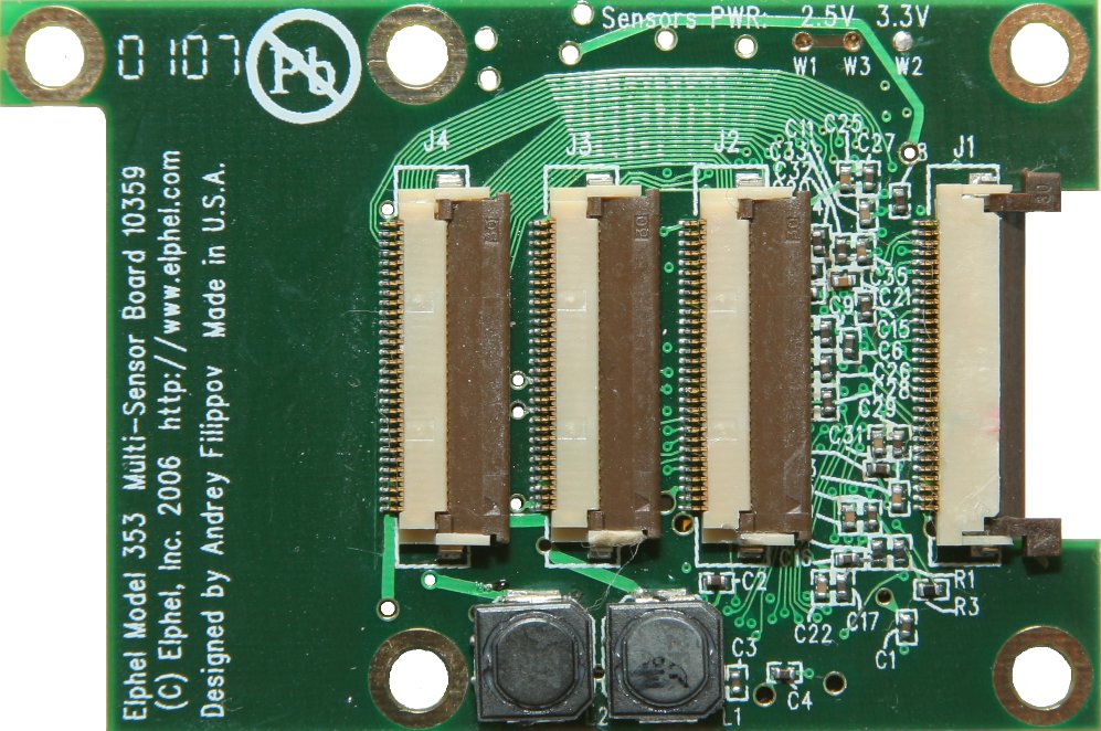
10359
Fix
There was an error discovered in 2011 in the 10359 & 10359A boards - due to a wrong source the sensors (J2,J3,J4) were powered from the 10359's 2.5V instead of the correct 3V coming from 10353 - the result was almost not noticeable - vertical stripes with a 4-pixel period (only with 10338d boards) - FixGuide.
10359B - 10359 Circuit Diagram, 10359 Gerber files
10359


10359 is an optional multi-function board for Elphel Model 393 Cameras and Elphel Model 353/363 Cameras. For 10393, also see using 10359 with 10393. It can be connected between the 10353 Processor board and a sensor one (up to three sensor boards can be connected) This board has the same FPGA-DDR SDRAM pair as on the 10353 (Processor) board. It uses just one extra conductor in the flex cable to configure the on-board FPGA, rest of the JTAG programming interface pins share connections with the data signals. This board can fit in the standard camera enclosure (when only one sensor board is used) and does not interfere with the boards that use inter-board connectors (i.e. 10357) - the 10359 is mounted on the other side of the 10353 board.
10359 board can be used in the following applications (as well as other ones):
- Additional custom image processing in the FPGA without the requirement to recompile the main FPGA on the 10353 board and solve possible conflicts with existent functionality.
- multiplex several sensor boards (i.e. "day" - color and "night" - monochrome) to one 10353 camera board.
- simultaneously acquire images from up to 3 sensors, compress them and send out one after another
- extract 3-d information from multiple sensors in real time in FPGA
- use additional sensor(s) to run correlation code (like in optical mice) to track camera orientation to compensate for the effect of Electronic_Rolling_Shutter
- connect earlier sensor boards (with 3.3V interface) to the 10353 board. Interface voltage for the sensor boards can be switched from 2.5V to 3.3V (all 3 simultaneously)
Connectors:
- 30-pin flex cable connector (J1) for data to/from the 10353 Processor board. It also receives 3.3V power through this connector
- 3 of 30-pin flex cable connectors (J2, J3, J4) for the flex cables to the sensor boards (i.e. 10338, 10347)
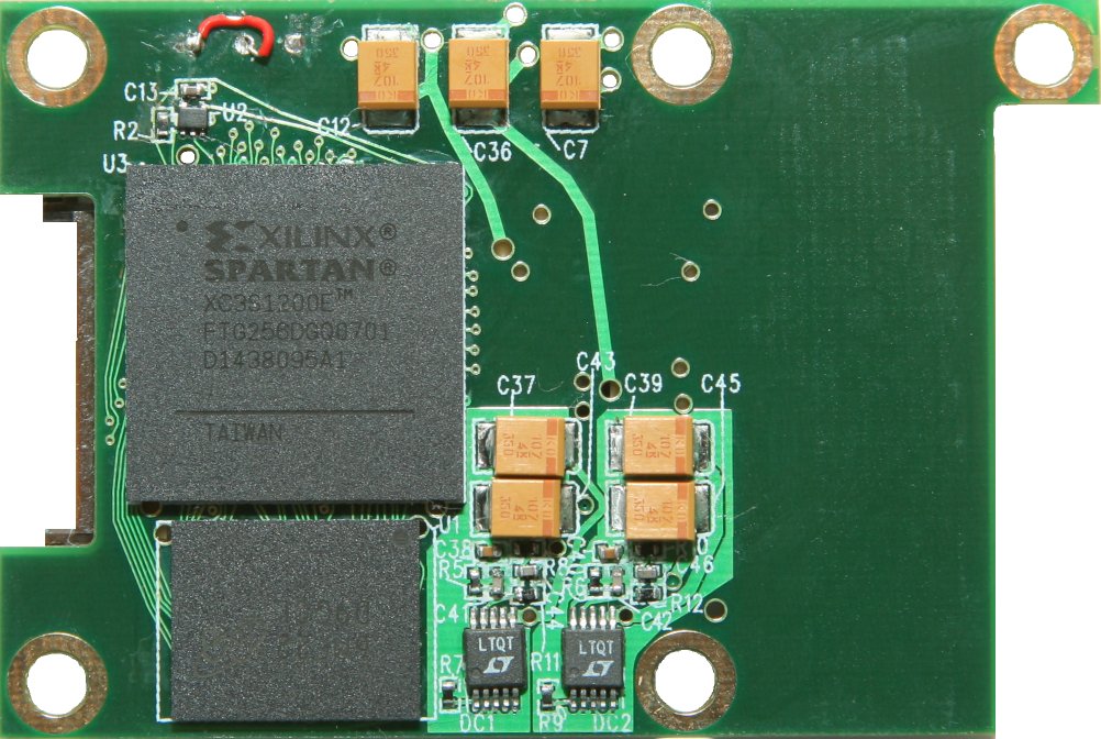
Spartan3E:
Power consumption
Idle (programmed): 3.3V 0.19A
Connect 10353, 10359 and sensors
Note: FPC cables we provide are not symmetrical (neither faces nor ends). Check the pictures below for correct cables connection.
 |
 |
Basic:
- Using a standard 30-pin flex cable connect 10353.J1 (connector's foil wires face away from the board) and 10359.J1 (foil wires face up)
- Using a standard 30-pin flex cable connect 10359.J2 (foil wires face down) and 10338.J1 (foil wires face up) (port 0 sensor, which is used for initialization)
Note: (after power on everything should work - frames from 10338 are transfered to 10353 as in 10338-10353 set up)
Optional:
- Using a standard 30-pin flex cable connect 10359.J3 (foil wires face down) and 10338.J1 (foil wires face up) (port 1 sensor)
- Using a standard 30-pin flex cable connect 10359.J4 (foil wires face down) and 10338.J1 (foil wires face up) (port 2 sensor)
Available modes
1. Program sensors either all at the same time or independently.
2. Switching between 3 direct (w/o buffering in 10359 DDR SDRAM) data streams from sensors.
3. Direct alternation mode (frames from 2 sensors alternate with programmable sequence).
4. Alternation mode with buffering:
- frames from 2 sensors alternate - one frame is stored in DDR SDRAM while another is direct)
- frames from 2 sensors are combined into one resulting frame vertically
Note: Vertical parts can be aligned by setting individual starting rows & lines to each sensor.
Controls page
For firmware versions >8.0.5.2 there's a page with controls:
- http://192.168.0.9/359/10359_controls.html
Scripts for 10359
- /359/phases_adjust.php?dcm=DCM&n=N&phase_shift=PHASE_SHIFT - adjusts phases for appropriate channels.
DCM=1 - channel 0 (J2)
DCM=2 - channel 1 (J3)
DCM=3 - channel 2 (J4)
N - number of single phase steps
PHASE_SHIFT=1 - positive step
PHASE_SHIFT=2 - negative step
- /test/test_inner_10359.php - automatic phases adjustment for all channels.
Tests
Projects with 10359
Training
- I2C module - master/slave/transparent
- DDR SDRAM controller - read/write/refresh/init
- Simple filters - invert
- Multiplexing sensors - switching between 3 sensors
- Image rotating/rescaling
Other
Installing 10359 inside 10353 body
 |
 |
 |
 |