Difference between revisions of "Using the cameras"
(→General Controls) |
|||
| (19 intermediate revisions by 3 users not shown) | |||
| Line 1: | Line 1: | ||
| + | {{Manual legacy_pages}} | ||
| + | |||
{{Manual Header}} | {{Manual Header}} | ||
| Line 7: | Line 9: | ||
== Complete set == | == Complete set == | ||
| − | The complete camera delivery set includes the actual network camera Elphel- | + | The complete camera delivery set includes the actual network camera Elphel-353/363, and Live-DVD with a special edition of the GNU/Linux operating system Ubuntu, complete with all the necessary software for the camera. |
The complete delivery set can also include lenses, an external power unit and connection cables for an additional payment. | The complete delivery set can also include lenses, an external power unit and connection cables for an additional payment. | ||
| Line 13: | Line 15: | ||
== Appearance == | == Appearance == | ||
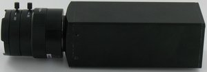
| − | [[Image: | + | [[Image:Elphel2.jpg|thumb|Elphel NC353L network camera]] The Elphel NC353L camera case is folding and made of anodized aluminium. Overall dimensions 116х45х45 mm, weight approximately 150 g (without lens). |
[[Image:Cam front.jpg]] The carving socket for standard C/CS-mount lenses is located on the front of the camera. | [[Image:Cam front.jpg]] The carving socket for standard C/CS-mount lenses is located on the front of the camera. | ||
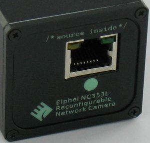
| − | [[Image: | + | [[Image:Elphel3.jpg|thumb|Back side of the Elphel NC353L network camera]] On the back side of the camera case are located a socket for connection of a network cable, a switch-on push button for the software reloading mode, and camera's model number mark. We constantly improve our products, therefore the number and appearance of the elements placed on the back panel can change. |
On the bottom of the camera case is the standard carving socket for installation of the camera on a support. | On the bottom of the camera case is the standard carving socket for installation of the camera on a support. | ||
| Line 23: | Line 25: | ||
== Connection == | == Connection == | ||
| − | + | 48V DC power supplies are used to provide power to the Elphel cameras, using the same cable as that used for network connection. | |
The Elphel camera has a standard RJ-45 Ethernet port, and can be connected to a local network. This port is also used to provide power to the camera. You can do it in two ways: | The Elphel camera has a standard RJ-45 Ethernet port, and can be connected to a local network. This port is also used to provide power to the camera. You can do it in two ways: | ||
| Line 29: | Line 31: | ||
1. Use the external power supply with integral DC Injector | 1. Use the external power supply with integral DC Injector | ||
| − | 2. Use | + | 2. Use a switch with integrated 48V DC Injector (IEEE802.3af compatibility is possible with an optional PoE module from Linear Devices) |
=== External power supply === | === External power supply === | ||
| Line 35: | Line 37: | ||
[[image:power_supply.png]] | [[image:power_supply.png]] | ||
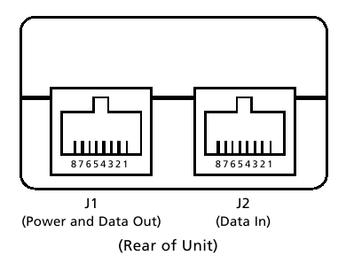
| − | The power supply has two built in RJ-45 jacks. J1 jack provides 48VDC and is used for connection to camera. You must use CAT5 "Crossover" cable for connection between J1 and the camera's RJ-45 jack. | + | The power supply has two built in RJ-45 jacks. J1 jack provides 48VDC and is used for connection to camera (IEEE802.3af compatibility is possible with an optional PoE module from Linear Devices). You must use CAT5 "Crossover" cable for connection between J1 and the camera's RJ-45 jack. |
J2 jack is used for connection to a hub/switch. You must use standard CAT5 cable for connection between J2 and the hub/switch RJ-45 jack. | J2 jack is used for connection to a hub/switch. You must use standard CAT5 cable for connection between J2 and the hub/switch RJ-45 jack. | ||
| − | + | switches have special RJ-45 jacks which provide the 48VDC PoE (IEEE802.3af). You must use standard CAT5 cable for connection between the switch special RJ-45 jacks and the camera's RJ-45 jack. | |
| − | |||
| − | |||
| − | |||
| − | |||
=== Necessary cables === | === Necessary cables === | ||
| − | |||
[[image:cable.jpg]] | [[image:cable.jpg]] | ||
Two cable types are necessary for Elphel cameras - standard CAT5 cable and CAT5 "Crossover" cable if ''the camera is connected directly to the computer''. Crossover cable is the same as used to connect two computers together with a single cable. If the camera is connected to a switch/hub (directly to the powered switch or through additional ''midspan'' power supply) no crossover cable is needed, all cables are straight. | Two cable types are necessary for Elphel cameras - standard CAT5 cable and CAT5 "Crossover" cable if ''the camera is connected directly to the computer''. Crossover cable is the same as used to connect two computers together with a single cable. If the camera is connected to a switch/hub (directly to the powered switch or through additional ''midspan'' power supply) no crossover cable is needed, all cables are straight. | ||
| − | |||
| − | |||
How to wire a "Crossover" Cable. | How to wire a "Crossover" Cable. | ||
| Line 104: | Line 99: | ||
The first color listed in the color pair is the dominant color of the wire. In other words, WHT/ORG is a white wire with orange stripes. | The first color listed in the color pair is the dominant color of the wire. In other words, WHT/ORG is a white wire with orange stripes. | ||
| + | |||
| + | *Pin 7 and 8 (Brown Pair): Power (+) | ||
| + | *Pin 4 and 5 (Blue Pair): Ground (-) | ||
| + | |||
| + | For further information about CAT5 Cables, try this link: [http://www.trangobroadband.com/infobase/cable_pinouts.shtml Cable Standards and Pin out] | ||
== Main Control Page == | == Main Control Page == | ||
| Line 132: | Line 132: | ||
[[Image:Aeblue.png]] - The autoexposure control window is opened | [[Image:Aeblue.png]] - The autoexposure control window is opened | ||
| + | |||
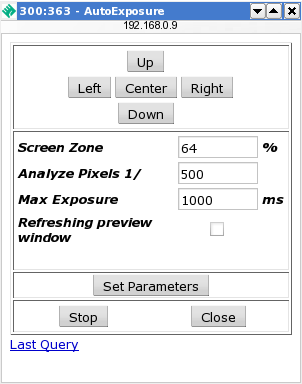
| + | When Autoexposure window is opened, the area of exposure calculating is appeared in the '''Window''' section. | ||
| + | |||
| + | In the Autoexposure window there are a few buttons for positioning the area of exposure calculating. The fields below are used for settings changing of the exposure calculating. | ||
| + | |||
| + | In the '''Screen zone''' field you can change the area which should be used for exposure calculating (in percents). | ||
| + | |||
| + | In the '''Analyze pixels 1/_number_''' field you can specify the amount of pixels which will be used for overlightening. | ||
| + | |||
| + | In the '''Max exposure''' field you can specify the maximal exposure time (in ms). | ||
| + | |||
| + | </td> | ||
| + | <td> | ||
[[Image:Autoexp_1.png]] | [[Image:Autoexp_1.png]] | ||
| Line 149: | Line 162: | ||
In the '''Image size''' drop-down menu you may choose the static window size. | In the '''Image size''' drop-down menu you may choose the static window size. | ||
| − | In the '''Resolution''' section there are a drop-down menu containing a few parameters (from 0 to 8) for changing resolution. 0 - full | + | In the '''Resolution''' section there are a drop-down menu containing a few parameters (from 0 to 8) for changing sensor decimation (resolution). 0 - full sensor decimation, 2 - 1/2 of full sensor decimation, 3 - 1/3 of full sensor decimation etc. |
| − | In the '''Binning''' section there are a drop-down menu containing a few parameters (from 0 to 3) which change the binning mode. | + | In the '''Binning''' section there are a drop-down menu containing a few parameters (from 0 to 3) which change the binning mode. Binning can be used only when decimation is greater than 1. Increases sensor sensitivity by combining values from several pixels instead of just discarding them (as done with just decimation). |
| − | |||
| − | |||
| − | |||
| − | |||
| − | |||
| − | |||
| − | |||
| − | |||
| − | |||
| − | |||
| − | |||
| − | |||
| − | |||
| − | |||
| − | |||
| − | |||
| − | |||
| − | |||
| − | |||
| − | |||
| − | |||
| − | |||
| − | |||
| − | |||
[[Image:Color.jpg]] In monochrome mode (when the '''Color''' radiobutton is not checked) "R" gain settings are used for all channels and color conversion is disabled. | [[Image:Color.jpg]] In monochrome mode (when the '''Color''' radiobutton is not checked) "R" gain settings are used for all channels and color conversion is disabled. | ||
| Line 219: | Line 208: | ||
''NOTE: Some parameters (e.g. window size) cannot be changed without stopping the acquisition/compression.'' | ''NOTE: Some parameters (e.g. window size) cannot be changed without stopping the acquisition/compression.'' | ||
| − | == Technical Information for the Elphel- | + | == Technical Information for the Elphel-353 == |
=== Default Setup === | === Default Setup === | ||
| Line 233: | Line 222: | ||
23/telnet | 23/telnet | ||
| − | 80/http | + | 80/http (lighttpd web server) |
| + | 82/http (boa ) | ||
=== Logging in === | === Logging in === | ||
| Line 246: | Line 236: | ||
=== Serial port === | === Serial port === | ||
| − | The serial port settings (additional board | + | The serial port settings (additional IO board [[10349]] is needed) |
Speed: 19200 8N1 | Speed: 19200 8N1 | ||
| Line 264: | Line 254: | ||
=== Multicast routing in Linux === | === Multicast routing in Linux === | ||
| − | In order to | + | In order to receive the multicast streaming from the cameras, you need to add the following route rule to an attached PC: |
route add -net 224.0.0.0 netmask 240.0.0.0 <interface> | route add -net 224.0.0.0 netmask 240.0.0.0 <interface> | ||
where <interface> is the interface connected to the camera (e.g. eth0). | where <interface> is the interface connected to the camera (e.g. eth0). | ||
| − | The | + | The [[ElphelSoftwareKit]] live DVD does this for you automatically. |
---- | ---- | ||
''Free Software and Open Hardware. Elphel, Inc., 2005'' | ''Free Software and Open Hardware. Elphel, Inc., 2005'' | ||
Latest revision as of 22:48, 7 May 2008
This is a legacy page. The information bellow is not compatible with Elphel 393 or 353/363 series cameras.
353/363 | Using the cameras | Camera software | Live CD | Camera hardware | Diagnostic & repair | Development documentation | 333 prices | Information | FAQ | About Elphel, Inc
Contents
Introduction
Elphel network cameras — complex devices in whose development advanced technologies and non-standard program decisions are used. We constantly improve our products so that users can use the cameras with the least expense of time and effort. In this section of Elphel Network Cameras Manual you can find detailed information about using Elphel cameras.
Complete set
The complete camera delivery set includes the actual network camera Elphel-353/363, and Live-DVD with a special edition of the GNU/Linux operating system Ubuntu, complete with all the necessary software for the camera.
The complete delivery set can also include lenses, an external power unit and connection cables for an additional payment.
Appearance
The Elphel NC353L camera case is folding and made of anodized aluminium. Overall dimensions 116х45х45 mm, weight approximately 150 g (without lens).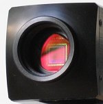 The carving socket for standard C/CS-mount lenses is located on the front of the camera.
On the bottom of the camera case is the standard carving socket for installation of the camera on a support.
Connection
48V DC power supplies are used to provide power to the Elphel cameras, using the same cable as that used for network connection.
The Elphel camera has a standard RJ-45 Ethernet port, and can be connected to a local network. This port is also used to provide power to the camera. You can do it in two ways:
1. Use the external power supply with integral DC Injector
2. Use a switch with integrated 48V DC Injector (IEEE802.3af compatibility is possible with an optional PoE module from Linear Devices)
External power supply
The power supply has two built in RJ-45 jacks. J1 jack provides 48VDC and is used for connection to camera (IEEE802.3af compatibility is possible with an optional PoE module from Linear Devices). You must use CAT5 "Crossover" cable for connection between J1 and the camera's RJ-45 jack.
J2 jack is used for connection to a hub/switch. You must use standard CAT5 cable for connection between J2 and the hub/switch RJ-45 jack.
switches have special RJ-45 jacks which provide the 48VDC PoE (IEEE802.3af). You must use standard CAT5 cable for connection between the switch special RJ-45 jacks and the camera's RJ-45 jack.
Necessary cables
Two cable types are necessary for Elphel cameras - standard CAT5 cable and CAT5 "Crossover" cable if the camera is connected directly to the computer. Crossover cable is the same as used to connect two computers together with a single cable. If the camera is connected to a switch/hub (directly to the powered switch or through additional midspan power supply) no crossover cable is needed, all cables are straight.
How to wire a "Crossover" Cable.
|
connector #1
|
connector #2
|
|
1 WHT/ORG |
1 WHT/GRN |
Color abbreviations:
WHT-WHITE
BRN-BROWN
ORG-ORANGE
GRN-GREEN
BLU-BLUE
The first color listed in the color pair is the dominant color of the wire. In other words, WHT/ORG is a white wire with orange stripes.
- Pin 7 and 8 (Brown Pair): Power (+)
- Pin 4 and 5 (Blue Pair): Ground (-)
For further information about CAT5 Cables, try this link: Cable Standards and Pin out
Main Control Page
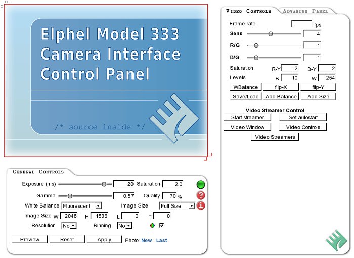
The Main Control Page uses javaScript to process user input (input fields and window of interest that can be selected by dragging a frame with the mouse), and combines all the camera acquisition parameters in a single GET request to a CGI program in the camera through the embedded web server (Boa). Currently the camera does not support simultaneous access as each request actually controls the camera operation mode (including sensor resolution and frame rate) and does not just connect to the camera output.
Page layout
On the top part of the page you should see a preview image. It is always 640x512, 800x600 or 512x386 pixels (1/2 or 1/4 of camera resolution depending on the sensor) and does not change with the selected decimation and window of interest (red rectangle over the image).
Below the preview image there are the camera controls:
General Controls
In the Window section there are 2 buttons at the bottom-right corner of window. You may specify window of interest (WOI) by dragging these buttons with the mouse. You may also change it numerically by entering data to W(idth), H(eight), L(eft) and T(op) input fields below. That numbers are rounded according to the selected sensor decimation and to use integer multiples of 16x16 pixels MCUs in JPEG compression. You may also change WOI by choosing one of the frequently used size from the list.
In the Exposure field there is an input field to specify frame exposure time (in ms) - it is possible to specify fractions. You may change this parameter by dragging the slider with the mouse.
Saturation section allows adjusting contrast saturation.
Gamma field controls contrast by adjusting intensity conversion, gamma=1.0 corresponds to linear response (high contrast). Values less than 1 increase input dynamic range by expanding low intensity values (low contrast). You may change this parameter by dragging the slider with the mouse.
JPEG Quality sets standard JPEG compression quality. The higher the quality the bigger the resulting file. It does not change the camera frame rate.
White balance section is a drop-down menu containing four static parameters: Sunlight, Cloudy, Incandenscent and Fluorescent. You can choose one of these parameters to achieve the highest quality image depending on the lighting conditions.
In the Image size drop-down menu you may choose the static window size.
In the Resolution section there are a drop-down menu containing a few parameters (from 0 to 8) for changing sensor decimation (resolution). 0 - full sensor decimation, 2 - 1/2 of full sensor decimation, 3 - 1/3 of full sensor decimation etc.
In the Binning section there are a drop-down menu containing a few parameters (from 0 to 3) which change the binning mode. Binning can be used only when decimation is greater than 1. Increases sensor sensitivity by combining values from several pixels instead of just discarding them (as done with just decimation).
![]() In monochrome mode (when the Color radiobutton is not checked) "R" gain settings are used for all channels and color conversion is disabled.
In monochrome mode (when the Color radiobutton is not checked) "R" gain settings are used for all channels and color conversion is disabled.
Below are 3 buttons Preview, Reset and Apply. Preview button refreshes the image in the top portion on a page (ignoring selected WOI and decimation), The Reset button returns to the initial adjustment parameters. The Apply button is used to accept the new changes.
Also there are two links after Photo: New contains a link to a camera CGI program that has all the acquisition parameters attached. You may just click it to open the image in a new window or right-click it and select "Save link target as..." (or equivalent) to save the image on your computer. The second link Last points to the last image already in the camera memory; you may use it to save the previously aquired image to your hard drive.
![]() button opens the information window where there is a list of the acquisition parameters used during the last image/clip acquisition.
button opens the information window where there is a list of the acquisition parameters used during the last image/clip acquisition.
Video Controls
Video Controls in this section allow users to record a video clip in the camera memory and send it over the LAN/Internet as a Quicktime video file. All settings for the image size, resolution, compression quality, analog gains and exposure are the same as for still images described above, and that link adds extra parameters - Frame Rate and Time Scale. The first sets the desired frame rate (leave blank or set to 0 for the maximal rate), the second field sets how much the playback time is longer than the acquisition one. I.e. setting of "10" makes the clip play 10 times slower that it was shot.
Total size of the clip (6-7MB) is determined by a camera internal buffer used for compressed image storage and the total number of frames as the frame headers are attached during the clip output and are not stored in the buffer. There are 2 ways to shoot a clip (usual duration 3-5 sec, depending on compression quality). First is to press Start stream button, wait for the event to occur and then press Acquire. In this mode after Start stream the camera continuously writes to the buffer, overwriting footage when all the available space is used. Pressing the Stop stream button ends data saving and so the buffer contains the last data recorded. Another way is to press Acquire before the event. In that mode the clip recording starts after the trigger and stops when the whole buffer is full.
There are additional controls to preview a videoclip from the camera memory. Frame number 1 is the first one, 2 - second, etc. Frame number 0 is the last one in the clip, -1 - previous before last, etc. Any image acquisition (including Preview) erases the stored clip and makes it one frame long.
Clicking on the Video Clip link opens the clip in the Apple QuickTime ™ (or compatible) player plugin (if installed) - you may also use this link to save the clip as a file on your computer.
Advanced Panel
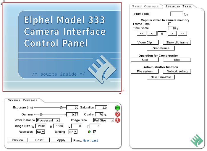
Advanced Panel tab opens additional adjustment parameters for the image. In this section you may specify more exact adjustments of color levels of the image.
Gains section controls the sensor analog gain settings. R, G and B input fields control color component gains. Using high gain settings increases sensor noise but is required to view fast events with 1ms exposure time with the lighting used in the current setup.
R-Y specifies color saturation for red color component.
B-Y specifies color saturation for blue color component.
B specifies color saturation for blue color component.
W specifies level saturation for white color component.
The Flip-X button allows turning the image horizontally.
The Flip-Y button allows turning the image vertically.
NOTE: Some parameters (e.g. window size) cannot be changed without stopping the acquisition/compression.
Technical Information for the Elphel-353
Default Setup
The default IP address of the camera is 192.168.0.9 netmask 255.255.255.0
You should be able to ping the camera from another machine on the same subnet.
By default, the following TCP ports are open:
21/ftp
23/telnet
80/http (lighttpd web server)
82/http (boa )
Logging in
You can log in to the camera via telnet on TCP port 23
User: root
Password: pass
Serial port
The serial port settings (additional IO board 10349 is needed)
Speed: 19200 8N1
RTS/CTS: None
XON/XOFF : None
Changing IP address of the camera
The camera network settings can be changed by going to:
http://<camera_ip>/axis.html
from an attached computer.
Multicast routing in Linux
In order to receive the multicast streaming from the cameras, you need to add the following route rule to an attached PC:
route add -net 224.0.0.0 netmask 240.0.0.0 <interface>
where <interface> is the interface connected to the camera (e.g. eth0).
The ElphelSoftwareKit live DVD does this for you automatically.
Free Software and Open Hardware. Elphel, Inc., 2005
