Difference between revisions of "Development documentation"
(→Motorized lens control) |
(→Motorized lens control) |
||
| Line 48: | Line 48: | ||
- lens control board [[10331]] | - lens control board [[10331]] | ||
| + | |||
| + | [[Изображение:10331_dev.jpg]] | ||
- power and communication board [[10332]] | - power and communication board [[10332]] | ||
| + | |||
| + | [[Изображение:10332_dev.jpg]] | ||
| + | |||
| + | Camera with motorized lens. | ||
| + | |||
| + | [[Изображение:Camera_with_motolens.jpg]] | ||
== Outdoor enclosure == | == Outdoor enclosure == | ||
Revision as of 17:52, 15 February 2006
353/363 | Using the cameras | Camera software | Live CD | Camera hardware | Diagnostic & repair | Development documentation | 333 prices | Information | FAQ | About Elphel, Inc
Contents
Introduction
2 Developers:
We just started this Wiki so the info here is rather patchy covering just some particular topics. Please be sure more will be posted here by us - Elphel develpers and (I hope) by you too.
Happy hacking of Elphel products,
Andrey
Photo-finish
Background:
The photo finish camera can be used for many sporting applications: greyhound, horse, bike, car/motorbike and athletics. This discussion will be focused on athletics competitions since this is the most demanding. The photo finish camera system “yet to be named” should meet all the requirements of a Fully Automatic Timer (F.A.T.) as outlined in the IAAF, and other international athletic organizations. A handful of such systems are available and are out of the reach of many small struggling clubs and sporting bodies.
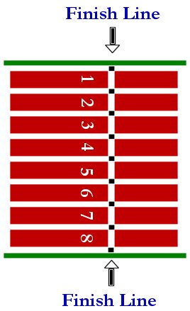
The photo finish camera is positioned at the finish line and takes continuous images of the line at a rate of 3072 frames per second and then displays them side by side on the screen. Since there are usually 8 lanes in the race the camera/software has to have some way of differentiating the lanes from the background. The simplest way is to paint the finish line with back squares where the lane line intersects the finish line for the software to detect the lanes and assign the athlete to the correct lane.
The photo finish images are composed of many assembled pictures of the finish line. Since the finish line is white and the lines that define the different lanes are also white it would be hard to differentiate the two. So the black squares would be seen as a continuous black line behind the athletes and would define the individual lanes.
The black squares on the finish line are also used for the camera alignment. The smaller the black squares the better the camera alignment.
Components of the photo finish system:
1. Camera – with high accuracy crystal IC- Timer (Elphel) and time stamping of images.
  - Remote controlled Pan tilt system for camera alignment (software and joystick control)
  - Remote control zoom lens (software)
  - Scope or laser for alignment
  - Restart button/trigger (wireless???)
2. Start/stop/reset trigger (wireless and/or mechanical).
3. Software- dedicated meet management system (a database driven image capture/analysis system).
SOFTWARE
Zeroconf for Elphel cameras
Elphel cameras and Zoneminder
USB host interface
Motorized lens control
- lens control board 10331
- power and communication board 10332
Camera with motorized lens.
Изображение:Camera_with_motolens.jpg
Outdoor enclosure
Real Time Clock for the camera
There is a description of RTC implemented in the camera FPGA. This clock might be fine-tuned, the data is available for reading by the CPU and to be embedded in the camera images/video by the FPGA itself.
Free Software and Open Hardware. Elphel, Inc., 2005
