Difference between revisions of "10393"
(→Supported Image Sensors) |
(→Supported Image Sensors) |
||
| (2 intermediate revisions by the same user not shown) | |||
| Line 17: | Line 17: | ||
* [[10398]]: [http://www.onsemi.com/PowerSolutions/product.do?id=MT9F002 MT9F002] - 14MPix 1/2.3" CMOS | * [[10398]]: [http://www.onsemi.com/PowerSolutions/product.do?id=MT9F002 MT9F002] - 14MPix 1/2.3" CMOS | ||
* [[103981]]: [http://www.onsemi.com/PowerSolutions/product.do?id=AR1820HS AR1820HS] - 18MPix 1/2.3" CMOS BSI ('' not yet manufactured'') | * [[103981]]: [http://www.onsemi.com/PowerSolutions/product.do?id=AR1820HS AR1820HS] - 18MPix 1/2.3" CMOS BSI ('' not yet manufactured'') | ||
| + | * [[10359]]: 3:1 Sensor multiplexer with memory, connects 3 of [[10338D]] SFE on each port, 12 sensors total | ||
====Memory and Storage==== | ====Memory and Storage==== | ||
| Line 34: | Line 35: | ||
** M.2 SATA port | ** M.2 SATA port | ||
** External synchronization (master or slave): | ** External synchronization (master or slave): | ||
| − | *** 2.5mm audio | + | *** 2.5mm audio connector/cable (4-conductor) |
*** 4-conductor flex cable | *** 4-conductor flex cable | ||
| − | ** 2x 10-conductor flex cable ports | + | ** 2x 10-conductor flex cable ports (USB, I²C, +5.0V, +3.3V, 2 × FPGA GPIO signals) |
*** carry 3.3VDC, 5VDC, USB, I<sup>2</sup>C and GPIO | *** carry 3.3VDC, 5VDC, USB, I<sup>2</sup>C and GPIO | ||
*** supports other extension boards ([[103695|IMU]], [[103696|GPS]]) | *** supports other extension boards ([[103695|IMU]], [[103696|GPS]]) | ||
Revision as of 19:13, 12 February 2018
Contents
About


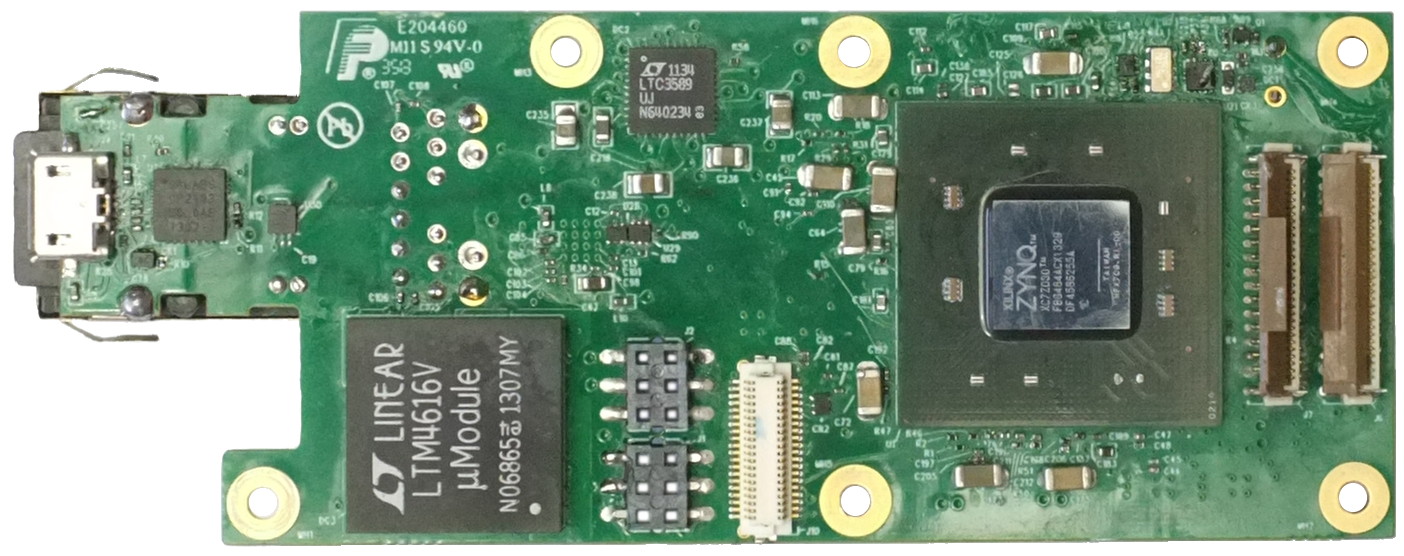
10393 is the system board of Elphel NC393 series camera. It is also the core part of the Eyesis4Pi 393, the full-sphere multi-camera system. It has the same physical dimensions as the 10353 (previous generation) and may be used as an upgrade to the previous camera modules.
More information related to NC393 series is available here https://blog.elphel.com/category/model-393
Overview
Operating System
- OpenEmbedded Linux (built with Yocto Poky)
Processor
- Xilinx Zynq 7030 SoC
- Dual-core ARM Cortex-A9 + FPGA
- 800MHz
Supported Image Sensors
- 10338D: MT9P006 - 5MPix 1/2.5" CMOS, see fps-resolution table
- 10398: MT9F002 - 14MPix 1/2.3" CMOS
- 103981: AR1820HS - 18MPix 1/2.3" CMOS BSI ( not yet manufactured)
- 10359: 3:1 Sensor multiplexer with memory, connects 3 of 10338D SFE on each port, 12 sensors total
Memory and Storage
- 1.0 GB DDR3 memory - system RAM
- 0.5 GB DDR3 memory - FPGA RAM
- 1.0 GB NAND flash - program storage
- microSD card slot - storage and system recovery
Interfaces

- Gigabit ethernet
- micro USB - system console (serial port), reboot, select boot device
- 4x sensor ports - routed to FPGA, each reconfigurable for general multi-purpose use
- Added by 10389 Extension board:
- USB2.0 (host)
- eSATA + USB port
- M.2 SATA port
- External synchronization (master or slave):
- 2.5mm audio connector/cable (4-conductor)
- 4-conductor flex cable
- 2x 10-conductor flex cable ports (USB, I²C, +5.0V, +3.3V, 2 × FPGA GPIO signals)
Other
- Compressor bandwidth - up to 1 GPix/s (e.g., processing 10MPix@100fps)
- Stream latency for 1080p@30fps - ~35ms + transfer and display times, see
~35ms takes for the camera to read out the image and compress (done in FPGA)
The transfer and display times: ~40ms
- Image formats: JPEG, JP4, RAW (coming)
- Wake-up on alarm
Power
- 3.3VDC
Physical properties
- Dimensions: 96x38x20.5 mm (with all connectors installed). Height can be reduced by removing the network connector.
- Weight: 31 g
- Mechanical drawings and CAD files for the 10393 board: link
SDK
- Firmware:
- Software (Kernel and Applications):
- Sources:
- SDK installation docs
User Manual
License
More details

This camera system board is designed to simultaneously support multiple sensors - both with legacy parallel interface (it is directly compatible with 10338 Sensor board and 10359 Sensor multiplexer board) and with new high-speed serial interface (up to 8 lanes + clock per each port), such as 10398 14MPix SFE. Sensor ports of the 10393 can be combined to interface larger/higher speed sensors, interface supply voltage is programmable in the range of 1.35V to 2.8V. All the sensor port interface signals are routed directly to the FPGA pads (22 I/O signals on each of the 4 flex cable connectors) , so the same ports can be uses for other purposes, for example to control the motors or interface IMU of the quadcopter.
Block diagram below shows major parts and I/O ports of the 10393 board. Left edge of the diagram corresponds to the sensor connections, right one - to the camera back panel with external connectors, top and bottom contain inter-board connections:
- The system is built around Xilinx Zynq 7030 SoC that combines a dual-core ARM processor, a rich set of the standard peripherals and FPGA on the same chip. This combination provides high bandwidth connection between the processors and the FPGA fabric.
- 4 identical sensor ports are 30-conductor 0.5mm pitch flex cable connectors, compatible with the earlier Elphel products. These connectors are split into two pairs, so they are closest to one short edge of the board - two on each side. Combined with an external multiplexer boards (at the expense of proportionally lower frame rate) each 10393 can work with up to 16 sensors (12 with the existing 10359 board).
- 500MB of the dedicated DDR3 memory chip is connected directly to the FPGA portion of the SoC, with the 16-channel image-optimized controller it provides efficient access to the memory for simultaneous image acquisition, compression and image processing. We plan to implement such functionality as real-time image de-warping and correlation of images from multiple sensors for the 3d data extraction.
- 1GB of DDR3 memory (2 chips providing 32-bit data bus) is uses as a system RAM for the processor subsystem.
- 500MB of NAND flash provide program storage.
- Persistent program storage is expandable with the micro-SD cards (not easy to see on the photo as the slot is hidden under the network connector). This interface provides bootable memory, so it is always possible to restore the camera functionality even if the system NAND will be accidentally flashed with corrupted image.
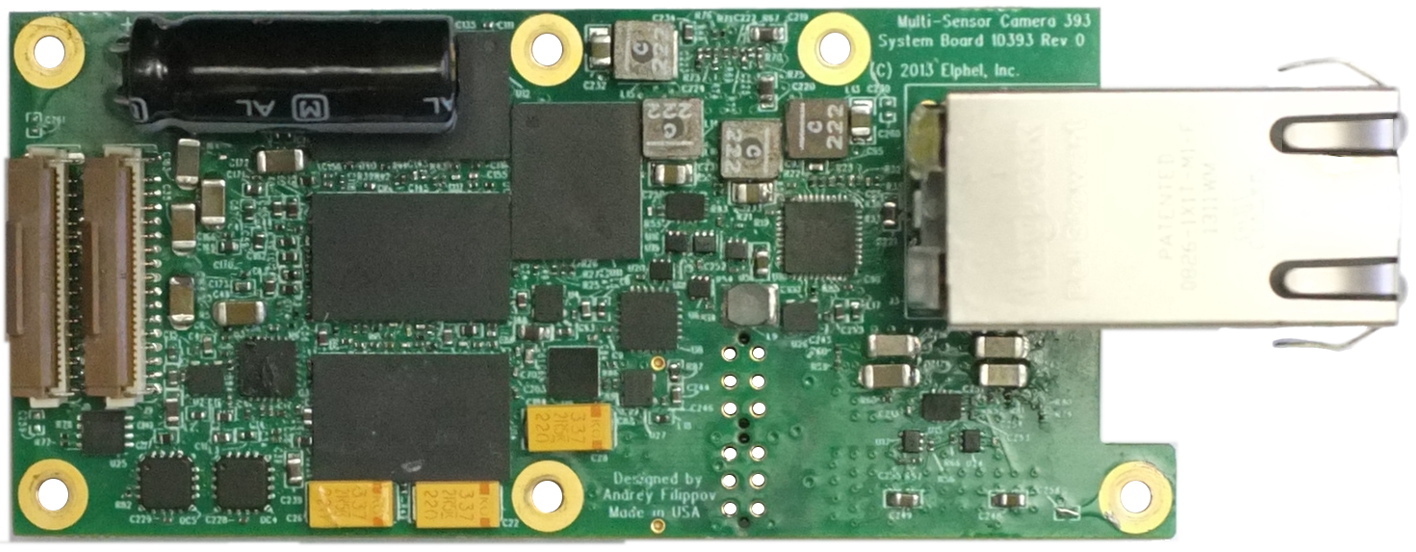
- Largest visible component on the board is the RJ45 connector for the Gigabit Ethernet, containing all the required magnetics (transformers) that are compatible with the PoE application. The peculiar shape of the board near connector is designed that it can be used with the hardware of the sealed RJ45 connectors.
- On the other side of the PCB under the RJ45 connector is the micro-USB connector type B (device) that can be used to implement a system console for camera software development. Additionally the USB-to-serial converter in on the 10393 board has GPIO functionality, it makes it possible to remotely reset/reboot the camera as well to as select the boot source (on the board NAND flash or external memory card). It also allows to build a fail-safe autonomous system with a camera reset-over-USB generated by a different master.
- 10353 uses 3.3VDC as a primary power source. All other voltages required by the SoC and other subsystems are generated from this primary 3.3 by the "Secondary power module" that includes fixed and adjustable by the software (over i2c bus) voltages, some voltages (such as sensor power) can be programmatically turned on or off. Primary 3.3VDC are provided by a separate 10385 power supply board that can be shut down by the software and awaken by an alarm signal from the clock/calendar.
- Clock/calendar uses a super-capacitor (large black cylinder on the bottom view photo) to provide power when the camera is turned off. This allows camera to be used to record time-lapse images during extended periods with only a battery, possibly combined with a small solar panel.
- Extension port uses a high-density 40-pin connector to interface a 10389 Extension board. It provides USB (host) signals, SATA channel, system i2c and GPIO signals from the FPGA. Extension board provides:
- SSD mass storage in m.2 SATA form-factor (up to 2260 - 22mm x 60mm).
- USB host (micro-A) external connector.
- eSATA/USB combo connector that can be used to connect USB flash drives, external HDD/SDD (powered externally or by USB 5.0V power) and host computer for high-speed data transfer (SATA3.0 - 6GHz)form the internal SSD storage.
- Inter-camera external synchronization connector (2.5mm audio type).
- Inter-camera module synchronization with a 4-conductor flex cables.
- Two of the 10-conductor flex cable ports that carry 3.3VDC, 5.0VDC, USB, i2c and GPIO, compatible with existing 103695 IMU adapter and 103696 GPS adapter boards.
Modifications
Links
Known issues
- SATA issues (old ones, all fixed now)
- PCB assembly problems (manually corrected, to be considered during future production runs)