Eyesis4Pi data structure
Contents
[hide]Intro
Eyesis4Pi stores footage and GPS/IMU logs separately.
| Model | Footage storage | GPS/IMU log storage | Comments |
|---|---|---|---|
| Eyesis4PI | Host PC or 9x internal SSDs (if equipped) | Internal Compact Flash cards (2x16GB) | |
| Eyesis4PI-393 | Host PC or 3x internal/external SSDs (/dev/sda2 - no file system) | 3x internal/external SSDs (/dev/sda1 - ext4 partition) |
IMU/GPS logs
Features
- ~1 micro second precision
- Up to 4 source channels:
- IMU
- GPS
- Image Acquisition
- External General Purpose Input (e.g., odometer - 3..5V pulses)
Description
The FPGA-based Event Logger uses local clock for time-stamping, so each log entry (IMU, GPS, Image Acquisition and External Input) is recorded with timing info.
In a single camera each acquired image has a timestamp in its header (Exif). The log entry for images has this timestamp recorded at the logger (local) time.
Multiple cameras (e.g., Eyesis4π) are synchronized by the master camera to sub-microsecond, and each acquired also image has the master timestamp in Exif. The log entries for images (if logged in the camera other than master so with different local clock) have 2 fields - master timestamp (same as in image Exif) and local timestamp (same clock as used for IMU), so it is easy to match images with inertial data.
A typical log record has the following format:
[LocalTimeStamp] [SensorData]
Examples or parsed records:
[LocalTimeStamp]: IMU: [wX] [wY] [wZ]  [dAngleX] [dAngleY] [dAngleZ] [accelX] [accelY] [accelZ] [veloX] [veloY] [veloZ] [temperature]
[LocalTimeStamp]: GPS: [NMEA sentence]
[LocalTimeStamp]: SRC: [MasterTimeStamp]
Syncing with an external device (Eyesis4PI - 10353 based)
An external device (e.g., odometer) can be connected with a camera / camera rig.
The device have to send HTTP requests to be logged to the camera on http://192.168.0.221/imu_setup.php?msg=message_to_log (message is limited to 56 bytes) and 3..5V pulses on the two middle wires of the J15 connector. !! Make sure only the two middle wires are connected and the externals one are not. Since the camera's input trigger is optoisolated, but not the trigger output. !!
For testing purposes we used an Arduino Yún with Adafruit Ultimate GPS Logger Shield. The GPS was used only to send a PPS to the camera's J15 port while Arduino Yún was running a simple script such as:
echo "" > wifi.log ; i=0; while true; do wget http://192.168.0.221/imu_setup.php?msg=$i -O /dev/null -o /dev/null; echo $i ; echo $i >> wifi.log ; iwlist wlan0 scan >> wifi.log ; i=`expr $i + 1`; done
This script is logging an incrementing number both to the camera log and Yún's file system, WiFi scanning is also recorded to the Yún's log. So later both log files can be synchronized in post-processing.
How to record log on the camera
over network
(see http://192.168.0.9/logger_launcher.php source for options and details):
mount_point=/absolute_path - the path at which the storage is mounted (usb or nfs)
from command line (10393 only)
- START:
mkdir /www/pages/logs
cat /dev/imu > /www/pages/logs/test.log
- STOP:
CTRL-C or killall cat
View recorded logs (read_imu_log.php)
from 10393s camera
http://192.168.0.9/read_imu_log.php
- looks for logs in /www/pages/logs (automatically created on the first access)
- displays and filters messages - EXT, GPS (NMEA GPVTG, GPGSA, GPGGA, GPRMC), IMU, IMG (4 ports)
- can convert a log to a CSV file (is saved to PC)
Notes
- GPS data is written to both, the event log and the image header (Exif).
- IMU data is written only to the event log.
- Example IMU (ADIS16375) samples rate is 2460Hz.
- Example GPS receiver (Garmin 18x serial) samples rate is 5Hz in NMEA or other configured format.
Examples
Raw
Raw *.log files are found here
Parsed
parsed_log_example.txt (41.3MB) - here
Tools for parsing logs
Download one of the raw logs.
- PHP: Download read_imu_log.php_txt, rename it to *.php and run on a PC with PHP installed.
- Java: Download IMUDataProcessing project for Eclipse.
Images
Samples
Description
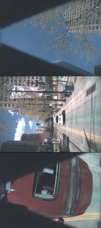
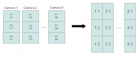
The pictures from each image sensor are stored in 8 triplets (because 3 sensors are connected to a single system board for the 24-sensor equipped camera) in the RAW JP4 format. ImageJ plugin deals with the triplet structure and does all reorientation automatically.
 JP4 file opened as JPEG - sample from the master camera. Download original JP4 Open in an online EXIF reader |
File names
Image filename is a timestamp of when it was taken plus the index of the camera (seconds_microseconds_index.jp4):
1334548426_780764_1.jp4
1334548426_780764_2.jp4
...
1334548426_780764_9.jp4
EXIF headers
The JP4 images from the 1st (master) camera have a standard EXIF header which contains all the image taking related information and is geotagged. So the GPS coordinates are present in both the GPS/IMU log and the EXIF header of the 1st camera images. Images from other cameras are not geotagged.
- Open the image from the master camera in an online EXIF viewer.
- Open the image from the secondary camera in an online EXIF viewer.
- The coordinates can be extracted from the images with a PHP script and a map KML file can be created.
Post-Processing
Requirements
- Linux OS (Kubuntu preferably).
- ImageJ.
- Elphel ImageJ Plugins.
- Put loci_tools.jar into ImageJ/plugins/.
- Put tiff_tags.jar into ImageJ/plugins/.
- Hugin tools - enblend.
- ImageMagick - convert.
- PHP
- Download calibration kernels for the current Eyesis4Pi. Example kernels and sensor files can be found here(~78GB, download everything).
- Download default-config.corr-xml from the same location.
- Download footage samples from here.
- Processed files are available for downloading from here (ready for the stitching step).
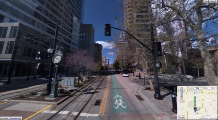
- Stitched results are found here.
Instructions(subject to changes soon)
- Launch ImageJ -> Plugins -> Compile & Run. Find and select EyesisCorrection.java.
- Restore button -> browse for default_config.corr-xml.
- Configure correction button - make sure that the following paths are set correctly (if not - mark the checkboxes - a dialog for each path will pop up):
Source files directory                - directory with the footage images
Sensor calibration directory          - [YOUR-PATH]/calibration/sensors
Aberration kernels (sharp) directory  - [YOUR-PATH]/calibration/aberration_kernels/sharp
Aberration kernels (smooth) directory - [YOUR-PATH]/calibration/aberration_kernels/smooth
Equirectangular maps directory(may be empty) - [YOUR-PATH]/calibration/equirectangular_maps (it should be created automatically if the w/r rights of [YOUR-PATH]/calibration allow)
- Configure warping -> rebuild map files - this will create maps in [YOUR-PATH]/calibration/equirectangular_maps. Will take ~5-10 minutes.
- Select source files -> select all the footage files to be processed.
- Process files to start the processing. Depending on the PC power can take ~40 minutes for a panorama of (24+2) images.
- After processing is done there is only the blending step - the following script scans directory for *.tiffs from ImageJ and uses enblend(to stitch into 16-bit tiffs) and convert them into jpegs, in terminal:
php stitch.php [source_directory] [destination_directory]
- no slashes in the end of the paths
Previewer
Note: This step is done independently from the processing and is not necessary if all the footage is to be post-processed. Just needs a KML file generated from the footage.
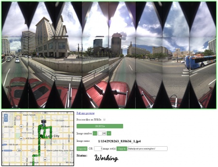
Here's an example of previewing the footage. If used on a local PC requires these tools to be installed.
Stitched panoramas Editor/Viewer
